
Mick Reeves 1/6 Scale Spitfire Review
|
 |
 |
 |
 |
 |
 |
| 1. Click to enlarge | 2. Click to enlarge | 3. Click to enlarge | 4. Click to enlarge | 5. Click to enlarge | 6. Click to enlarge |
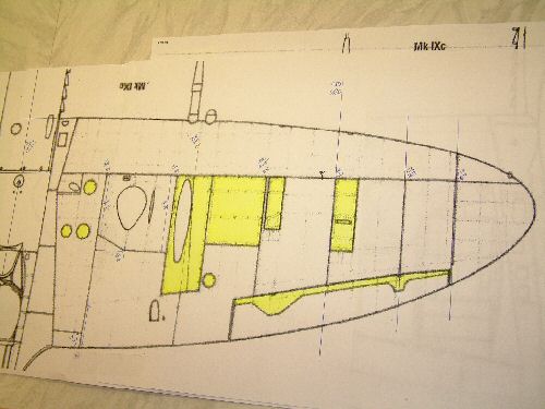
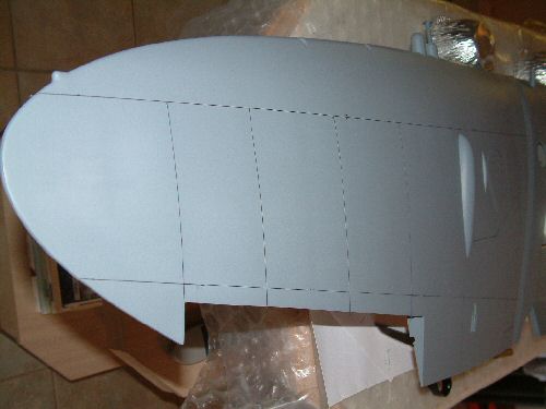
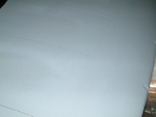
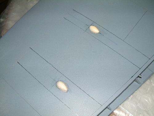
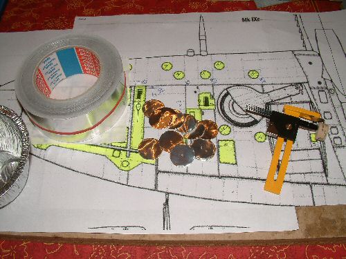
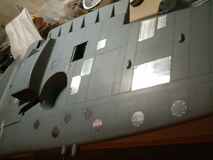
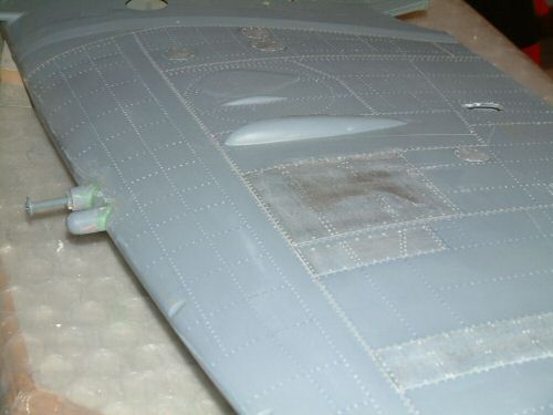
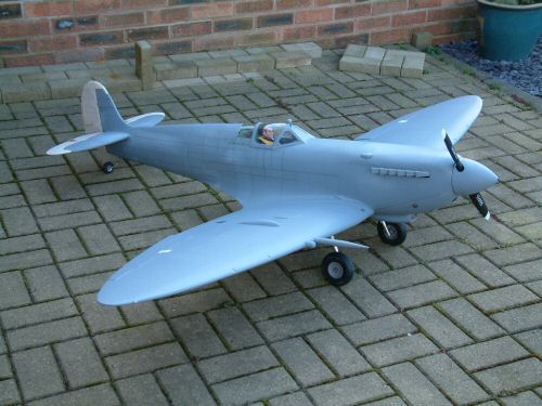
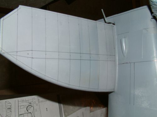
One of the bigger decisions was to decide on panel lanes only or panel limes and rivets. I am starting with the plan to do both. The first component ready for processing was the wing. Pic 1. SAM Publications Spitfire reference book - invaluable! Pic 2. An enlarged extract from the book provided 1/12 scale plans of the panel and rivet lines. I drew the panel lines on the wing with water based fibre tip pen. Any mistakes could then be erased with warm water. This was later traced over with 1/64" (0.4mm) tape. This process took 3 hours for the wing top and bottom. Pic 3. Shows the job well in hand & almost completed. 2 coats of filler primer and one of gray primer were applied. The surface was then sanded lightly before removing the tapes to save the paint from chipping. Pic 4. With the tape out the lines are nicely visible. Pic 5. Lower blisters were installed in position using epoxy on the underside of the wing. They need to be in the middle of a raised panel section so to simulate the edge of the panel I taped round the outline and primed the edges. This gave a nice ridge. Pic 6. There are a number of other flat panels and inspection hatches on the Spitfire and rather than build them all up with primer I am going to use aluminium tape cut to size and carefully applied to the surface. The round inspection hatches will be cut using a disc cutter. I got this procedure while following the build pages for a BT Spitfire by Sean of Strictly Scale - click here to go to his site. |
 |
 |
 |
 |
 |
 |
| 1. Click to enlarge | 2. Click to enlarge | 3. Click to enlarge | 4. Click to enlarge | 5. Click to enlarge | 6. Click to enlarge |
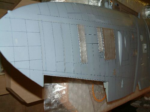
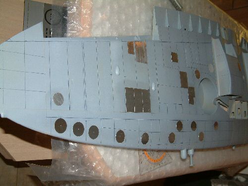
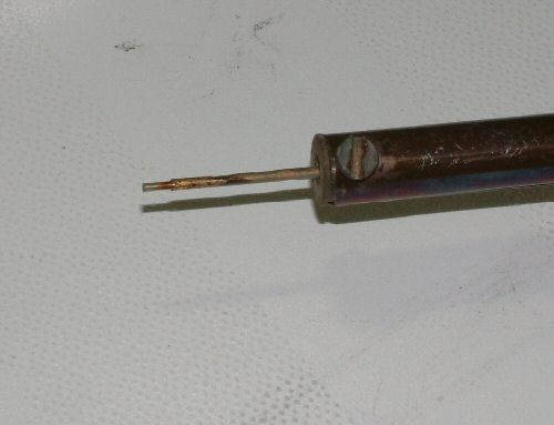
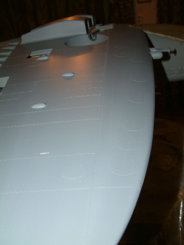
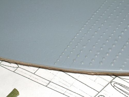
I decided the rivet lines had to go on so after much reference to the scale information, drawing and cutting began. A time consuming exercise to say the least! Pic 1. Shows the top surface & . . . Pic 2. The underside, ready to receive the rivets. I have made some concessions on the rivet lines as I made some errors matching the panel lines top to bottom (OK I measured something wrong!). I have decided not to go back and start again (too time consuming) but will have to accept some difference in the alignment of the rivets top to bottom. It's not that obvious, but I am sure someone will notice. Pic 3. The rivets were produced by making a small impression in the primer using a soldering iron with a modified tip. For scale the rivets need to be about 0.8mm diameter. The most suitable implement I could find was a inkjet printer refill needle which is slightly oversized with an OD of 0.95mm. The distance from the heating element was adjusted until the tip worked in a controlled way. Any shorter the tip temperature would have melted the paint too fast. I practiced on a test panel before committing to the actual wing. Pic 4. I am having a right riveting time, yes I know all those jokes now !! 25% done & going fine so far. This pic is relatively low resolution and does not do justice to the detail. If you want to see a higher resolution picture click here (109 KB). Pic 5. the top side complete (well that half anyway!) I have rubbed on some lightweight filler to fill the larger indentations and then wiped it off with a dry tissue. The plan is to lightly wet & dry the surface before a final primer coat , Pic 6. Duly applied primer and looking very nice :) Click here for high resolution version (60 KB). It will be allowed to stand to thoroughly dry for 2 weeks before I start spraying the top coats. Health warning - Rivets are time consuming! Now to tackle the fuselage. |
 |
 |
 |
 |
 |
 |
| 1. Click to enlarge | 2. Click to enlarge | 3. Click to enlarge | 4. Click to enlarge | 5. Click to enlarge | 6. Click to enlarge |
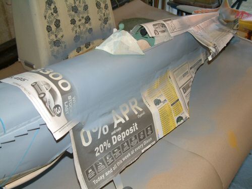
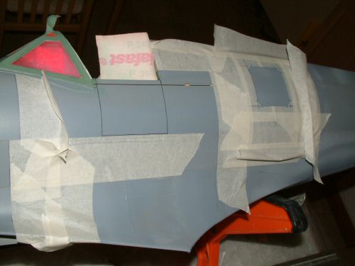
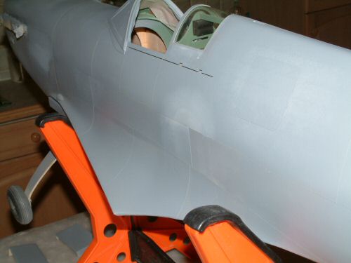
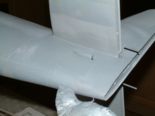
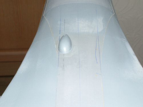
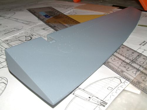
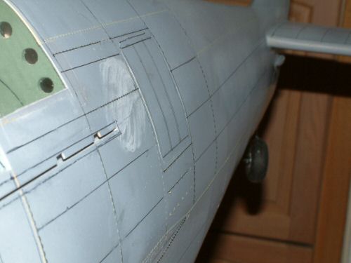
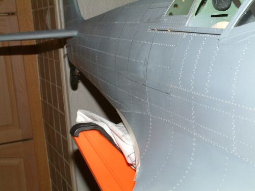
Pic 1. Starting with the panel lines on the fuse to get some texture for the rivet lines. Several stages were needed to get the multiple butt joints at the front and overlap joints elsewhere complete. This picture was taken at the first masking process. Pic 2. is about 4 stages later. Pic 3. the penultimate stage (6), and not looking too badly for it. Care has to be taken when planning the lines so that you maximise the spray areas without interrupting each other with masking tape. Generally happy, but building the layers has eaten away a full week of my spare time! Pic 4. A balsa cover for the rudder push rod was installed before the finishing touches of paint were applied. Pic 5. The last job was to install of a bulge to simulate the "Boat antenna" as it was known, on the underside. I have pre drilled the part for later installation of the short radio mast. Pic 6. The aileron with it's panel lines and inspection panels fabricated as per the wings. I also completed the landing flaps rivet lines (not shown). |
 |
 |
 |
 |
 |
 |
| 1. Click to enlarge | 2. Click to enlarge | 3. Click to enlarge | 4. Click to enlarge | 5. Click to enlarge | 6. Click to enlarge |
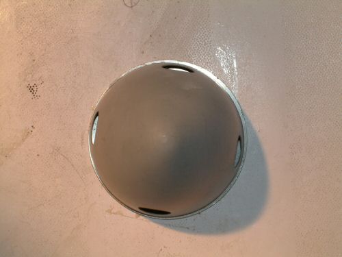
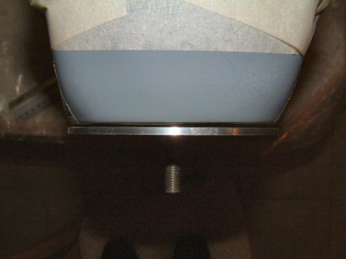
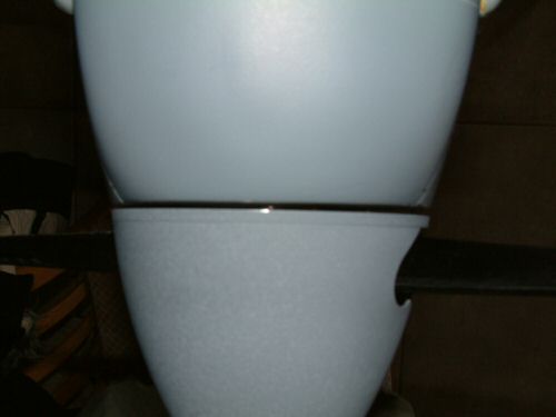
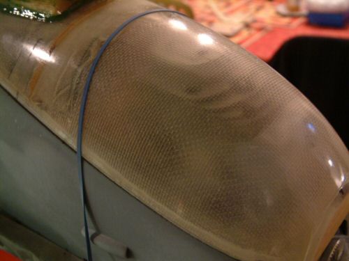
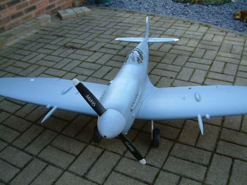
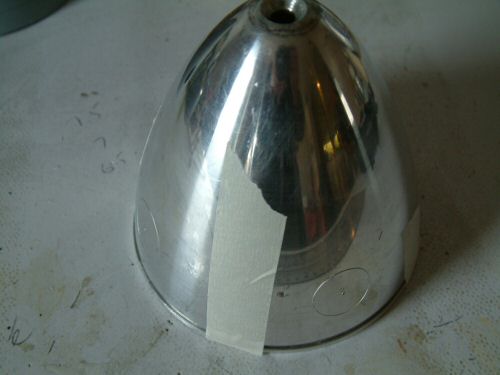
The replica spinner and props are all molded plastic. Pic 1. The spinner was cut from the sheet and leveled with minimum waste. Location marks were positioned at 90° to each other using reference points on a paper template. 20mm holes were cut at each point. Pic 2. A sheet of 1/8" ply was cut to fit in the spinner. 4 blocks of general purpose ply were cut to make a housing block to hold the props in position. Pic 3. The blades were assembled some time ago and during all stages of assembly where excess epoxy was available the hollow of the props was slowly filled to give some extra strength. They were then sanded and primed as seen in the picture. Pic 4. Test fitting the dummy spinner to the 4" aluminium spinner base revealed the dummy spinner 6mm shorter in diameter. This would show when fitted so I have scrapped the part. A replacement aluminium spinner was purchased which will be used for flying and the supplied Mick Reeves spinner will be used for the dummy. Pic 5. The 4" spinner viewed from the side has a good profile against the fuse, but from the to, as in the picture, an oversize is apparent. This was put right with some epoxy putty which was blended onto the fuselage sides, sanded and re-primed. Rather a disappointing situation really. Pic 6. Not that clear but after the filler was sanded and re-primed the mating of the spinner to the fuse was much more satisfying. |
 |
 |
 |
 |
 |
 |
| 1. Click to enlarge | 2. Click to enlarge | 3. Click to enlarge | 4. Click to enlarge | 5. Click to enlarge | 6. Click to enlarge |
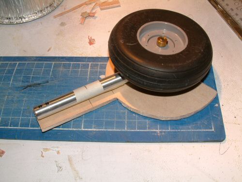
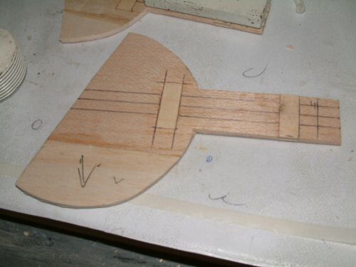
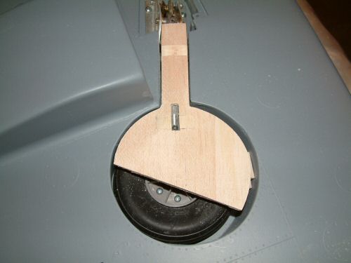
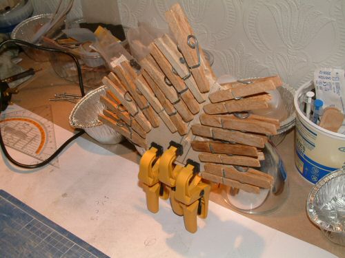
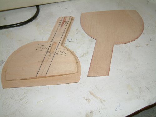
Next job is the wheel covers, which I originally intended to make from glass moulds previously cast over the wings before cutting the holes. They weren't much use in the end so I began construction from scratch (must try harder next time). To start with I took a template in paper from the wing and cut a section from 1/32" ply and 1/8" balsa and laminated them. Pic 1. Shows the alignment process marking the fit lines of the oleo legs. Pic 2. Sections of the balsa were removed for installation of strong ply where the mounting screws will fit. Pic 3. The section was trimmed to give good clearance from the walls of the wheel well. I then sanded a curve into the outer balsa sheet before applying the oversized outer 1/32" ply. Pic 4. Bad day for washing but a convenient day for clamping. I used Aliphatic glue for this lamination to see how strong the glue really is. I purchased it to have a go at raised rivets, but that's for later! Pic 5. Clamping off and the covers are now ready for installation of the brackets. The curve of the outer skin can be clearly seen. The Aliphatic glue has done a good job and I can confirm it sands much better than PVA, Pic 6. Glassed, primed, sanded, riveted, and cut to size. Looks as though it grew there (well almost!). I will use 4 x 2mm button head bolts to secure the covers with a brace when I can source the bolts. |
 |
 |
 |
 |
| 1. Click to enlarge | 2. Click to enlarge | 3. Click to enlarge | 4. Click to enlarge |
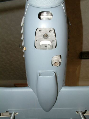
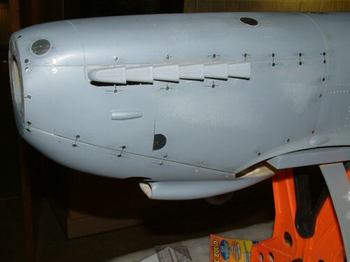
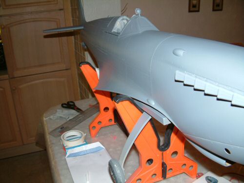
The front cowl is the last thing to sort out before applying the rivets. Pic 1. The Laser just fits within the confines of the cowl and the fins are just too close for the glass for comfort. This will require slightly large access holes than I would have preferred, but they have to be done. I also applied a fillet of epoxy and cloth off cuts along the joint between the cowl and fuse to close the gap that was there. Pic 2. After cutting, sanding and priming the cowl fitted well onto the fuse. Note also the needle side mounted from the starboard of the cowl. Pic 3 & 4. Dry fit looks OK and I am now ready for the riveting of the fuselage. |
 |
 |
 |
 |
 |
 |
| 1. Click to enlarge | 2. Click to enlarge | 3. Click to enlarge | 4. Click to enlarge | 5. Click to enlarge | 6. Click to enlarge |
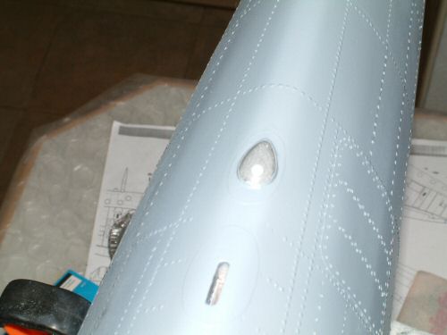
Having had reasonable success with the flat rivets on the wings I have decided to have a go at the raised rivets that are used on some parts of the Spitfires fuselage. Interestingly there is a combination of domed and flat rivets on a MKIX. From information received via a few forums the the number of domed rivets on a Spitfire declined to none from the beginning of the MKV to the end of the MKXVI. So I need to be somewhere in between. I used a very good picture of MH434 in a book called "Spitfire Flying legend" (got mine in a sale for £8.99). This proved to be a good guide for the placement of the rivets. Pic 1. Shows my experiments on my test panel starting on the right to the left as I changed application method and technique. I will practice a little more before committing to the model. I suppose an advantage of this method is that any mistakes can be washed away with a damp cloth! Pic 2. Application of the "live" items on the fuse. Pic 3. The final result, not that easy to see, but look reasonable at the moment. Pic 4. Lining out for the normal rivets on the rest of the fuse and tail surfaces. Without a right angle or one decent flat surface to reference this was a real challenge I can tell you. I used water based ink which washes off easy after a mistake which proved very useful, and because it can be removed it does not show up through the final primer coats. Pic 5. & Pic 6. Photo taken from starboard side where most of the riveting is complete. The surface has yet to be cut back with fine wet and dry to flatten ridges from the process. |
 |
 |
 |
 |
 |
| 1. Click to enlarge | 2. Click to enlarge | 3. Click to enlarge | 4. Click to enlarge | 5. Click to enlarge |
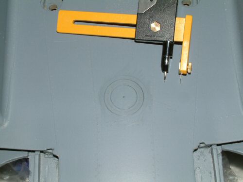
Some finishing touches. Pic 1. the top navigation light was installed using Zap-a-da-pa-Goo II. The bulb is a white pin head held in place with epoxy into a countersunk hole. Pic 2. the front removable panels have special fixing points (not sure what their correct name is). Several other round inspection panels were installed, including fuel filling point. That done I am ready to start with the final few rivets. Pic 3. Final prime before colour is applied. Pic 4. Ok so I forgot the downward identification light in the wing! drew out a template line and cut the wood with a the radius cutter. Put a sheet of ply in the bottom, followed by some printed foil to give the reflector some realism, and finally followed by a lamination of clear plastic coloured with some red lacquer. Pic 5. The top disc cut from 1/64" ply stock then sealed down with epoxy and sealer to fill the gaps. |
 |
 |
 |
 |
 |
| 1. Click to enlarge | 2. Click to enlarge | 3. Click to enlarge | 4. Click to enlarge | 5. Click to enlarge |
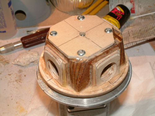
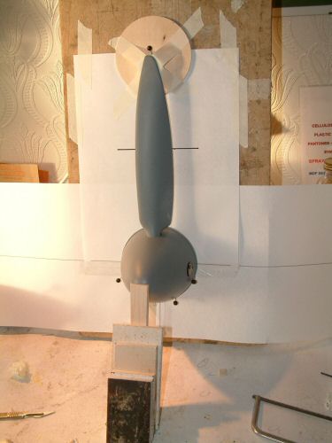
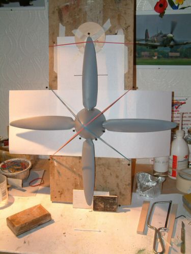
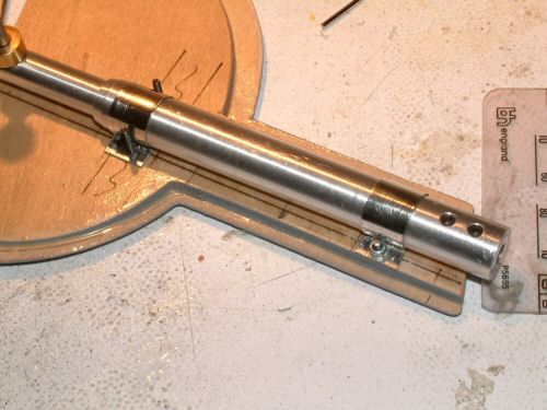
Having scrapped the idea of using the plastic replica spinner, I started to prepare the 4" aluminium spinner supplied with the kit. Pic 1. First job was to mark the position of the 4 X 20mm holes. These were measured using a paper template. for the job. Pic 2. The wooden block was drilled to accommodate the prop stubs, and some additional spacers of 1/8" ply were added for extra strength. The The ply base was held off the spinner plate 1/4" with scrap wood and held in place with 4 wood screws installed from the back plate into countersunk holes. It was very important to ensure all was true and central during this stage of assembly. The spinner is retained with the original screw which fastens into a bolt retained with epoxy in the wooden plate affixed to the top of the block. After the spinner was installed the screw at the tip of the prop was sanded round and some Epoxy Putty was used to fill in the remaining imperfections. The spinner was primed before applying some 1/64" tape to give some texture to the surface. 4 more coats of primer were applied where the tape was applied. Pic 3. The spinner was retained on a paper template on a building board vertically mounted. Individually the orifice at the top was flooded with epoxy before adding the prop. In this position the epoxy will overflow but will not flow out ensuring a good fix to each prop. After the epoxy hardened the assembly was rotated 90° to mount the next blade. Each time the prop was held in position with a shim to ensure the mounting was identical to the next. Pic 4. Shows the installation of the final blade. |