
YT International P51D - Tail SurfacesThe tail surfaces are are much like the wings and come ready decorated with the special film YT now use on all their scale warbirds. The covering will be stripped and the and re-covered just like the wings. |
 |
 |
 |
 |
 |
 |
| 1. Click to enlarge | 2. Click to enlarge | 3. Click to enlarge | 4. Click to enlarge | 5. Click to enlarge | 6. Click to enlarge |
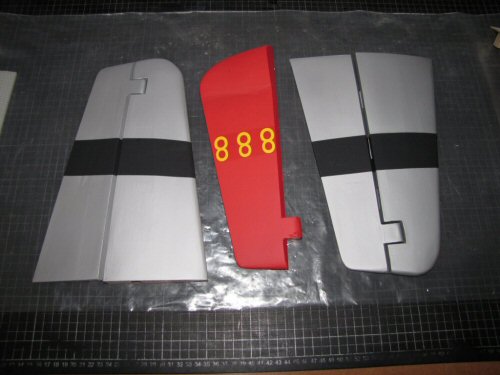
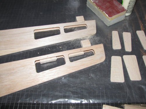
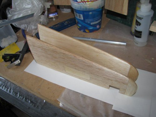
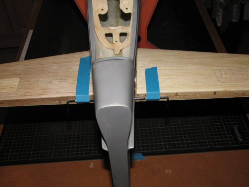
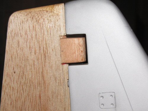
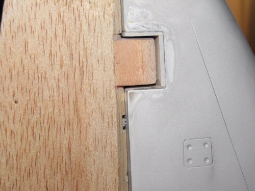
Pic 1. First thing to do is to strip the coverings from all the surfaces. Pic 2. All stripped back and prepared for modification. Pic 3. I will be upgrading the hinges to pinned hinges as with the ailerons, so some small blocks of soft balsa have been added to improve fixing security. The missing skin sheeting was replaced as with the wings with Aliphatic PVA. Pic 4. Seen here sanded and then sealed with z-poxy ready for glassing. Pic 5. The horizontal stabilisers are held in position with an aluminium tube and some dowel locators which have to be drilled and affixed. This process is aided with a small ply template included in the kit to get the holes perfectly aligned. Shown here the stabilizers are dry installed and the elevator control rod installed. This part comes ready assembled in the kit and includes 2 plastic guiders with wings that are fixed into the training edge to hold the bar steady. Grooves were cut into the wood so that the bulk of the plastic guiders allow the rod to run flush with the trailing edge. In this picture the plastic guiders are covered by the blue tape. Pic 6. The elevators were cut to accept standard pin hinges and aligned with the stabilisers. The factory drilled hole to accept the control rod was a good 4mm outward on both elevators so the holes had to be plugged and new holes cut to accept the rod. |
 |
 |
 |
 |
 |
 |
| 1. Click to enlarge | 2. Click to enlarge | 3. Click to enlarge | 4. Click to enlarge | 5. Click to enlarge | 6. Click to enlarge |
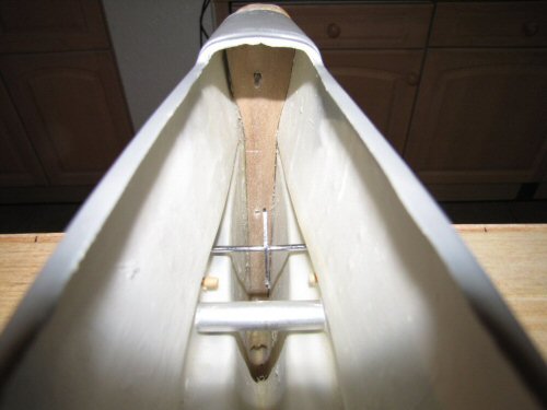
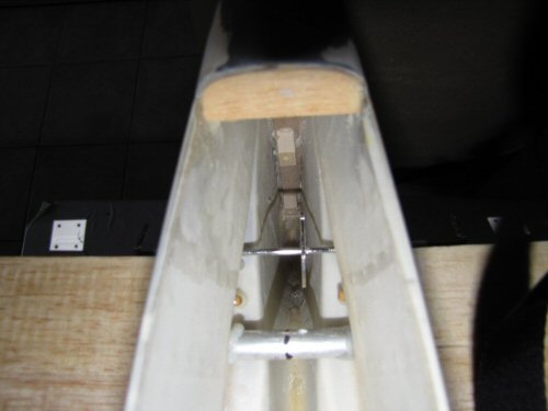
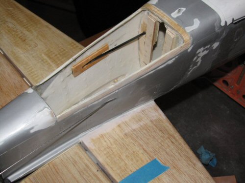
Pic 1. All installed with perfect free movement, something I feel felt hinges does not offer! The elevator parts will not be glued into position until all painting has been completed. Pic 2. The rudder will be held by 3 pin hinges slightly larger than those provided in the kit. Once fitted it can be seen that there is a lot of air around the weight post which will need filling in with some fillets of balsa. The weights on the elevators will need similar treatment though less pronounced than the rudder. Pic 3. Here the fillets are installed. Filler will be used to tidy the gaps up later. Pic 4. The root of the rudder post has a sheet of 3mm ply running up the inside and for me this will need some small blocks of light wood fixing to give better grip for the pin hinges. Pic 5. Duly installed the blocks now offer good support for the hinges. I installed them by passing a short length of string through the root of the fin, then feeding it through a pilot hole in a block and making a knot. With the epoxy was on the block I pulled on the string and it made the blocks fit in position with a little bit of extra encouragement to run relatively square. When dry the string was cut and drilled out! Pic 6. The Tail wheel sits on 2 ply rails I have added to the former in the fuselage to give it some extra strength. To ensure the rudder's Pull-Pull wires do not interfere with the operation of the tail wheel I have installed carbon tubes to guide the wires past the mechanism. This also provided a nice outlet for the wires from the fuselage as shown in the picture.
That's it for now on the tail end. Installation of the various components comes later on after the model has been painted. |