

YT International BF109E - as supplied parts |
 |
 |
 |
 |
 |
 |
| 1. Click to enlarge | 2. Click to enlarge | 3. Click to enlarge | 4. Click to enlarge | 5. Click to enlarge | 6. Click to enlarge |
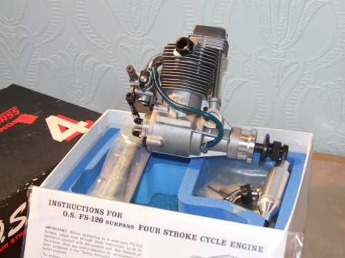
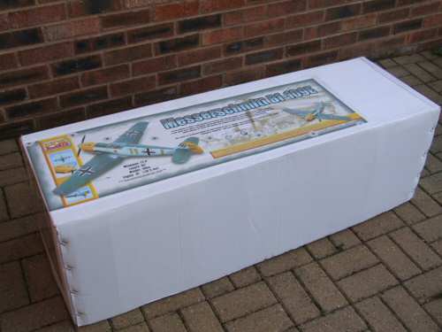
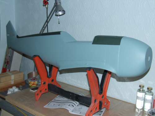
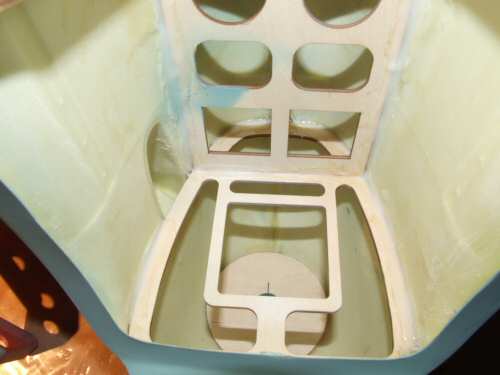
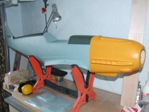
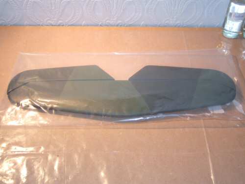
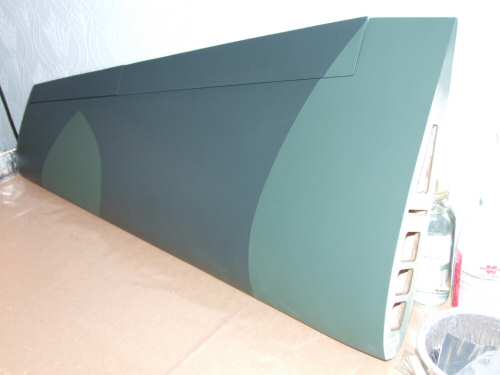
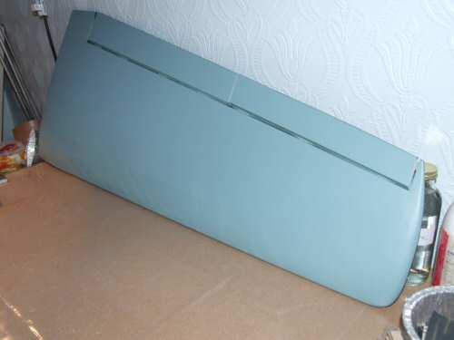
Pic 1. Before I open the box on the kit here is a shot of the OS120FS Surpass pumped engine I have acquired. Not the latest model but a good buy from eBay. I am planning on running it with a 2 blade 16 x 6 Master air screw. Pic 2. The YT Messerschmitt BF109E in it's box. It was actually delivered contained within another brown box which has since been re-cycled. No damage to the box was visible so I opened the box with confidence. Inside plenty of packaging and use of hot melt to hold everything in position, all in all a well thought out package! Pic 3. Starting with the fuselage we have an all glass construction, nicely finished to a high standard. It really looks like a canvas waiting for an artist . . . if you know what I mean! Pic 4. Internally, to the front and . . . . Pic 5, to the rear the formers are secured with real resin, none of your hot melt here. Not so sure the timber is in correct for the tail wheel, we shall see later. Pic 6. The large cowl is also finished to a good standard in a rather loud YELLOW finish. I was not planning to weather the surfaces, but this part is screaming for some grime to be rubbed in. |
 |
 |
 |
 |
 |
 |
| 1. Click to enlarge | 2. Click to enlarge | 3. Click to enlarge | 4. Click to enlarge | 5. Click to enlarge | 6. Click to enlarge |
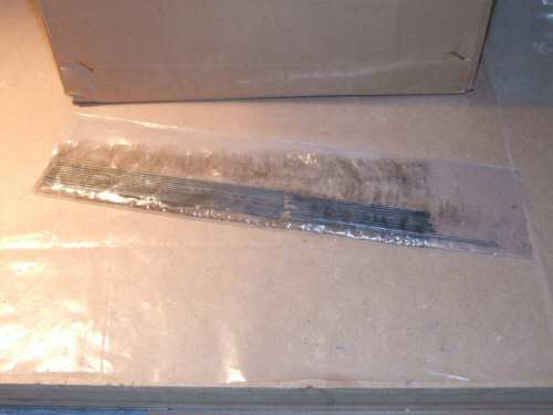
Pic 1. The cowl fits to the fuselage with a snug fit, absolutely perfect. Pic 2. The canopy is provided ready painted so there should not be too many issues there. Pic 3 & 4. Push rods, servo mounting blocks and other parts that only become apparent when you read the instructions ;-\ Pic 5. The wheel wells are made from clear plastic and install like a tray into the recess. I have seen comments on forums from people preferring to use 1/64" ply to line the wells. Highly likely that I will join them with this modification. Pic 6. The rudder is a fully prepared frame structure which should install with ease. |
 |
 |
 |
 |
 |
 |
| 1. Click to enlarge | 2. Click to enlarge | 3. Click to enlarge | 4. Click to enlarge | 5. Click to enlarge | 5. Click to enlarge |
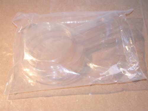
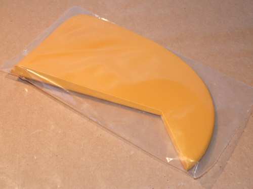
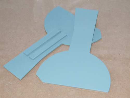
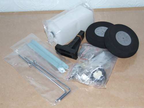
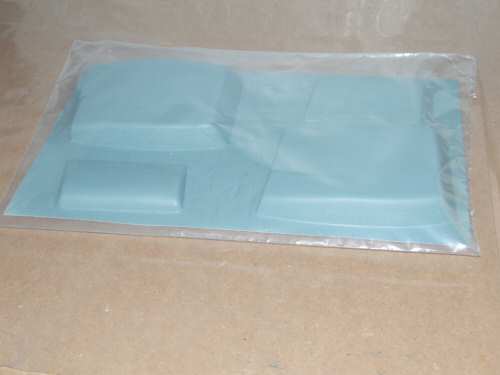
Pic 1. Next out are the wheel covers. they are a little rough on the inside showing some grain too, so I will re-finish these surfaces later. No major job really. Pic 2. The horizontal stab and elevator are fully built up frame structures as the rudder, all I will have to do is install the hinges and it's done! Nicely finished assembly. Pic 3. The wings top side is all sheeted covered in Solartex™ and then painted with what looks like an enamel paint. Pic 4. Wing underside is an open frame in some areas and finished as the top side. All access holes are pre cut as you would expect from an ARTF. Pic 5. First is the goody bag containing all the fasteners and fixings which look very reasonable through the plastic bag. Also there is a 550ml fuel tank, the foamy wheels, wire wheel struts, and glass filled resin engine mount. Pic 6. The Plastic "vac" formed parts for the air scoops under the wings. These will probably be replaced with wooden replacement units. |
 |
 |
| 1. Click to enlarge | 2. Click to enlarge |
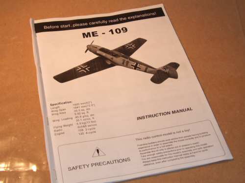
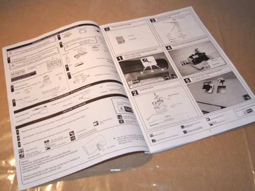
| Pic 1 & 2. Those all important instructions which you must "read carefully the explanations" . . .yes you sure know you have an ARTF with phrases like that on the front page. That aside they appear clear enough to me so should not pose any problems. |
 |
 |
 |
 |
 |
| 1. Click to enlarge | 2. Click to enlarge | 3. Click to enlarge | 4. Click to enlarge | 5. Click to enlarge |
| Optional parts available from YT International |
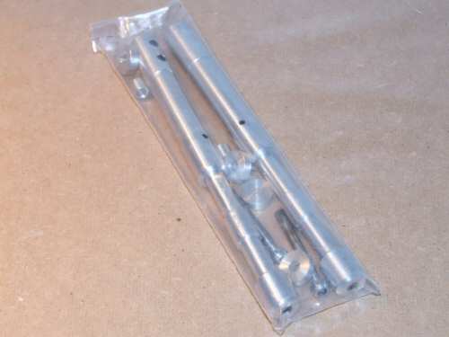
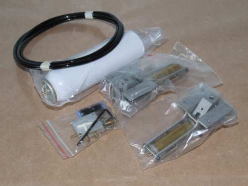
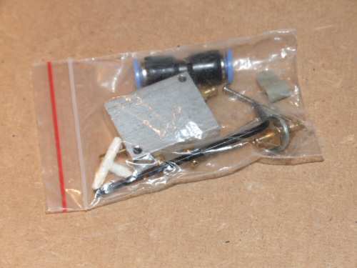
Pic 1. The optional spinner is very well presented, but does pose a challenge for the flyer wanting to squeeze those larger engines in with a big prop. The drive shaft of larger engines is known to catch on the recessed spinner mounting. YH have responded by supplying a shim seen here in the picture which sits behind the spinner making the shaft that little bit shorter. I will look at this closer to the time of installation. Pic 3. The retract system is a spring down air up systems and look like they are up to the challenge. They are however a standard 90° retract which is not true scale but for most people it will be sufficient. If I feel the need to, I will alter the units by putting wedges under the mounts. Everything needed is provided from what I can see. Pic 4. The retracts air valve looks like a small version of the Century Jets design I have for the BT Spitfire. There is only one way to assess this equipment so we will have to wait post installation testing. Pic 5. Close look at the retract unit. |
 |
 |
| 1. Click to enlarge | 2. Click to enlarge |
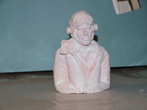
| More Optional parts sourced myself |
| 12/06/2006 |
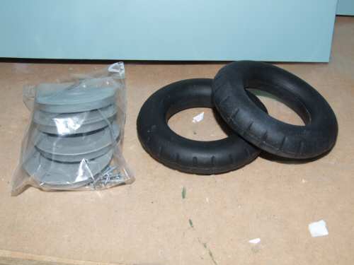
Pic 1. I found the supplied wheels a difficult combination with the OLEO legs to install, so I decided to get some replacement wheels. I found an alternative design from Graham at Tiger Models, who was very helpful. Pic 2. £10 pilot from Pete's Pilots via eBay. Seen here with a general white coat to seal the shell. I will not be getting carried away with the pilot detail, so long as he looks a little hostile that will do for me! |