
YT International BF109E - Post flight Modifications |
 |
Having got a few flights under the belt I am really happy with the model. Nice lines, well built kit, and easy to fly. Not bad for ARTF and the price! A few things need to be resolved however, but first it is important to stress none of them are faults with the kit or accessories, but modifications I want to make for personal reasons and to make permanent corrections to the retract modification which failed me during a heavy landing at RAF Coltishall. Other activities for this modification page will include:
Let's get started then . . . |
 |
 |
 |
 |
 |
 |
| 1. Click to enlarge | 2. Click to enlarge | 3. Click to enlarge | 4. Click to enlarge | 5. Click to enlarge | 6. Click to enlarge |
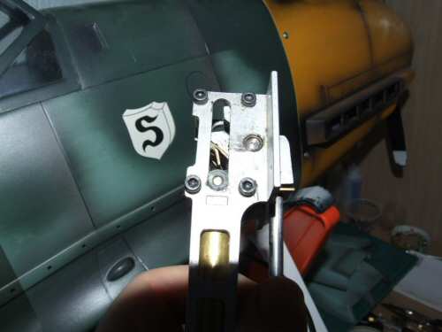
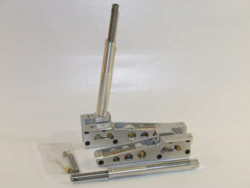
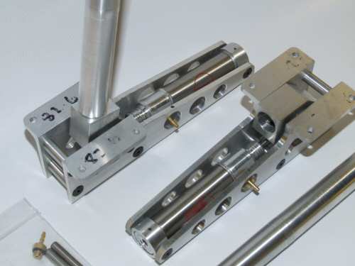
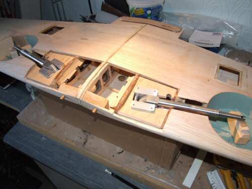
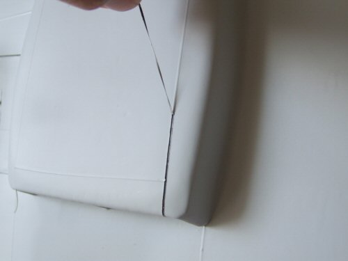
Pic 1. The YT supplied retracts were modified by me to make them hang at 80° rather than the default 90° as supplied. The modification is detailed on the wing page - click here. While the modification worked well on the bench it failed during a heavy landing which caused the brass shim to split open. I did folded the 1mm brass to make a 2mm shim using standard solder to hold it closed. It is possible that silver solder might not have failed, but regardless of that, I decided not to fight with them anymore and purchased a set of retracts from Lenny Shindin of Shindin Machine in the US. the retracts are first class, but can take 6 weeks to arrive so planning is necessary. Please also note: can now purchase 80° retracts direct from YT international which were not available at the time of this build: Click here for more details. Pic 2. Shows the retract units as supplied straight from the box. Pic 3. Closer view. The spring in the OLEO's are much lighter than the YT units, and operate with the traditional air up, air down system. That means the air valve will need to be replaced and fortunately I have a spare air valve for the job to hand. Pic 4. Time to strip the Solartex. Removal took about 40 minutes and left the wood relatively clean. Pic 5. All done. Pic 6. First thing is to clean up all the control surfaces hinge points. First the flaps and ailerons had the damaged wood cut out. |
 |
 |
 |
 |
 |
 |
| 1. Click to enlarge | 2. Click to enlarge | 3. Click to enlarge | 4. Click to enlarge | 5. Click to enlarge | 6. Click to enlarge |
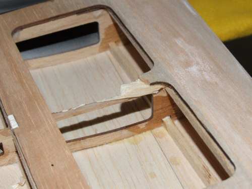
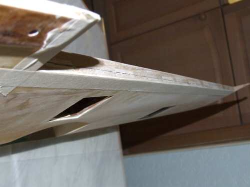
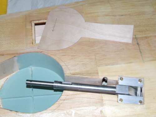
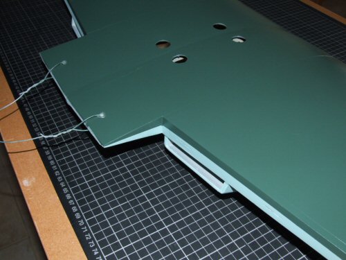
Pic 1. With fresh wood spliced in the Kavan medium sized hinges can be installed into new slots. Pic 2. Similarly the wing received newly grafted wood into the trailing edge for a fresh start. I was careful to follow the previous hinge lines when slotting to ensure everything remained perfectly aligned. Pic 3. The wheel well on the 109E is not round but a strange stretched "D" shape. I modified the lining accordingly. Some support was added behind these laminations of 1/64" ply to give them a better fixing. Pic 4. The canons will be mounted at 413mm from the wing root. Behind the leading edge I have installed a block of balsa (lamination of 3 x 1/4") to hold the mounting tube for the canon. I also added a sheet of 1/4" balsa spanning the main spars behind this block (forgot to take a picture!) which will be the rear most mount for the tube which will hold the canon true. Pic 5. While I was working in this area I installed some extra blocks to accept the hinges to provide more security. Pic 6. Naughty, Naughty. While cutting some redundant wood for the sheeting this rib had clearly been damaged in the factory and touched up with some scrap balsa. |
 |
 |
 |
 |
 |
 |
| 1. Click to enlarge | 2. Click to enlarge | 3. Click to enlarge | 4. Click to enlarge | 5. Click to enlarge | 6. Click to enlarge |
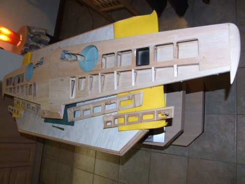
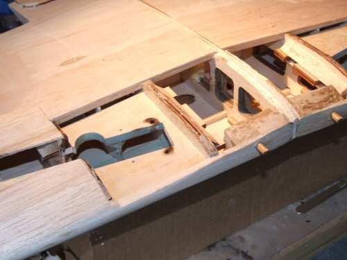
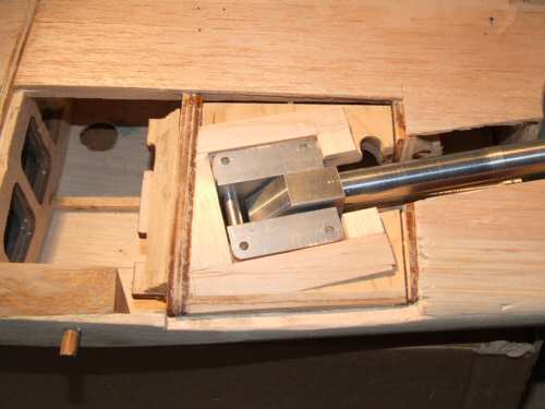
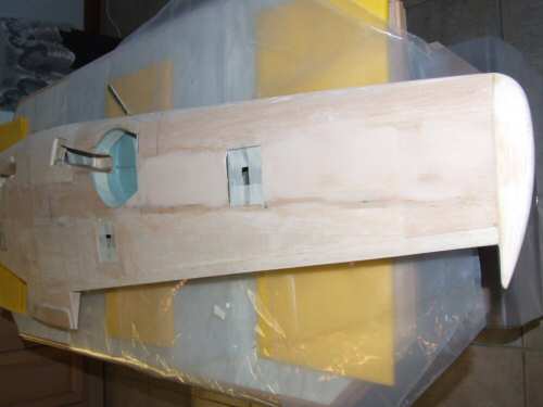
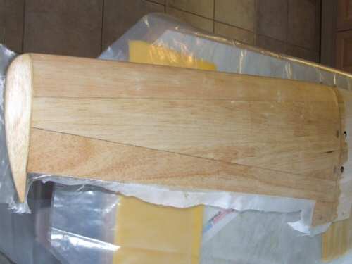
Before I start this section I want to point out that it is not necessary to strip the wing like this to make the Shindin retracts fit into the wings. I am doing this because I want to and have the opportunity to do so with the wing stripped! Pic 2. While installing the 1/16" sheet balsa I used some scrap sections to provide supports in relevant areas as shown here. This ensures the new sheet makes good alignment with the neighbouring wood. Pic 3. All sheeted & allowed to dry overnight. Pic.4. I am going to do a major rework of the retract mounting plate while the wing is stripped. To do this I am removing the sheeting and all the soft wood from the top of the main plate. The picture shows the extent of the stripping. Pic 5. It just so happens the Shindin retracts need a 1/4" shim to make them the correct height in the mountings so I cut from stock 1/4" Ply. More room is also needed in the hollow between the mounts and the well for these retracts so the Dremel proved to be a most useful friend for the job. The small cut out in the mount you can see is to permit easy installation of the retract air line that connects to a nipple on the side of the cylinder. Pic 6. Installed with a surround that has been sanded ready for final sheeting. |
 |
 |
 |
 |
 |
 |
| 1. Click to enlarge | 2. Click to enlarge | 3. Click to enlarge | 4. Click to enlarge | 5. Click to enlarge | 6. Click to enlarge |
Pic 1. After sheeting the area around the retract blocks I sanded and filled as necessary to improve the surface for glassing. Note also the masking tape in the wheel wells and servo hatches to make cleanup of the excess resin easier later on (well worth the tape!). Pic 2. A quick look at the retracts in position shows that they run out a little. It's not much and I think it will shim out at final installation. Pic 3. On with the glassing and the picture shows the first of the top sheets applied having previously completed the bottom surfaces. I am using 0.6oz cloth and Z poxy resin for this process. Pic 4. More masking in preparation for application of the trailing edge cloth. Pic 5. The ailerons and flaps had to be cleaned up to accept replacement hinges. To do this I was able to cut slabs out of the top surface of the aileron and then to splice in replacement sections with block balsa. Pic 6. The blocks were sanded to fit and the slots re-cut for the hinges. Note also I have installed bolts for servo connection removing the need for any fixings on the top of the wing. These were firmly secured in position with epoxy. |
 |
 |
 |
 |
 |
 |
| 1. Click to enlarge | 2. Click to enlarge | 3. Click to enlarge | 4. Click to enlarge | 5. Click to enlarge | 6. Click to enlarge |
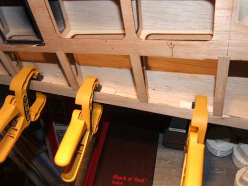
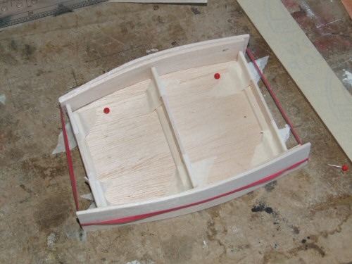
Pic 1. Before covering with Solartex I sealed the wood with Balsaloc to give improved adhesion of the cloth. Pic 2. As I cocked up the wheel covers last time I will remanufacture from scratch, only this time I will fit them the correct way round! So first off I started with the outline in 1/32" ply. Pic 3. Then create a balsa duplicate in firm 3/32" balsa (top of picture). Into the balsa I grafted solid 1/8" ply plates to add extra support where the fixing bolts will be located. Pic 4. The balsa is laminated using aliphatic glue onto the ply and held down in position over the OLEOS in their exact positions. A mixture of clamps, tape, and weights were used to achieve this. Pic 5. Clamps off after 24 hrs drying on the wing. This picture was taken after 20 minutes sanding to finish the profile off. Pic 6. The finished items. Both will be glassed on the outside in preparation for painting. |
 |
 |
 |
 |
 |
 |
| 1. Click to enlarge | 2. Click to enlarge | 3. Click to enlarge | 4. Click to enlarge | 5. Click to enlarge | 6. Click to enlarge |
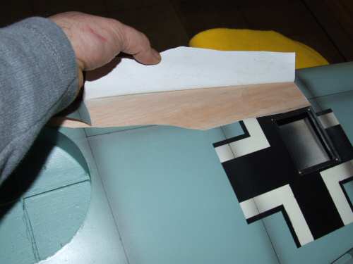
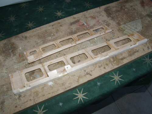
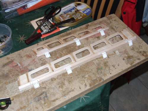
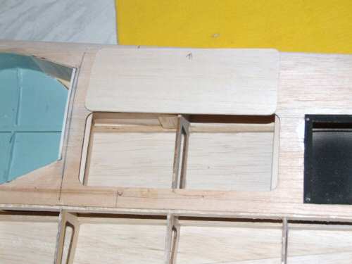
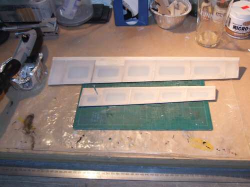
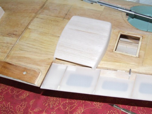
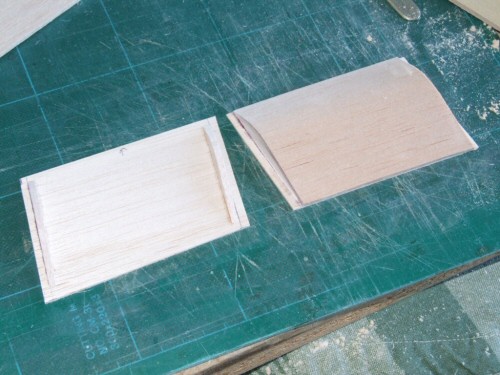
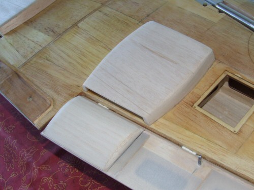
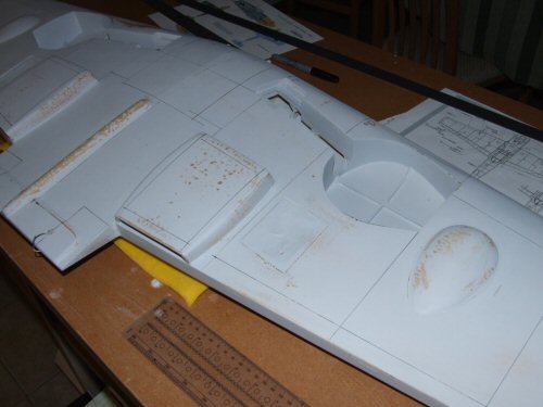
Pic 1. I was not a big fan of the plastic scoops the first time I installed them so I decided to make some from wood. I started with a rough framework to support the scoop using the plastic components as rough guides. Pic 2. Next I cut 2 strips of 3/32" balsa and laminated them while holding them around the framework to form the curve. Picture shows the 2 sides produced and ready for the next stage. I cut the sides down to meet the marked points on the frame and then fixed 1/8" sheet balsa over the formed curve shape. When it was dry I lifted it off the frame and made a second identical unit. Pic 3. Shows the finished scoop roughly located after a course sanding. Pic 4. The deflectors that fit onto the flaps were made from a sheet of 1/16" balsa with some 1/8" formers mounted 1/4" in from the edge seen here picture left. The inset would permit installation of some 1/4" sheet to apply a slight round to the edges. Over the top went a sheet of 1/16" balsa seen picture right. Pic 5. With the 1/4" applied to the ends I was able to round the corners for the desired effect. Pic 6. The scoops were trimmed at the trailing edge to follow the wing and sanded to conform to the wing. This sanding was achieved by laying a sheet of 230 grit on the wing and gently rubbing the scoop over the installation area. Once the profile was finished I added a small strip of 3mm light ply to simulate the central strut. |
 |
 |
 |
 |
 |
 |
| 1. Click to enlarge | 2. Click to enlarge | 3. Click to enlarge | 4. Click to enlarge | 5. Click to enlarge | 6. Click to enlarge |
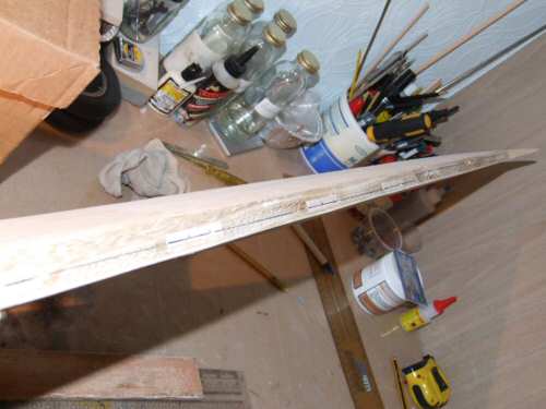
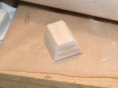
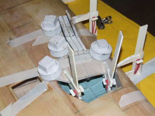
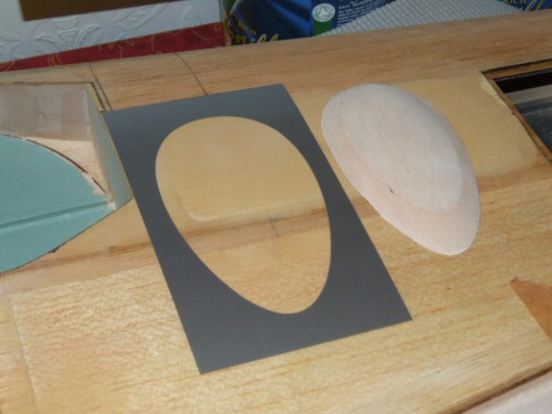
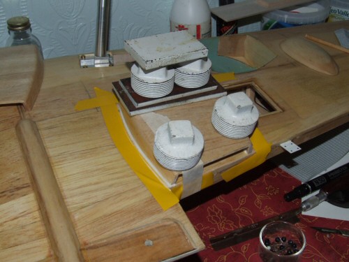
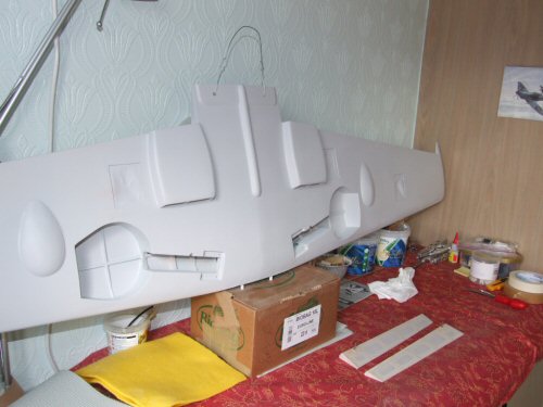
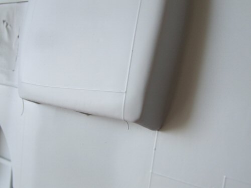
Pic 1. The final layout of the rads before fixing. Pic 2. Also on the underside of the wings there are 2 inspection blisters for the cannon. Not part of the original kit but I thought I might as well add some for the short time it take to manufacture. I took rough size measurements from an old copy of Aero Detail 1 and began to form the shape with 2 lumps of 1/4" soft balsa. Pic 3. I sanded the blister to shape and then sanded it to the profile of the wing using the same method as for the radiators. I made a slightly oversized mask for the wing to protect the surface from excess glue. Pic 4. Down root of the wing there is a raised bump. Not sure what it is all about but prominent enough for me to produce a facsimile on the model. I am sure it looks nothing like this but is will suffice. Made from a few strips of 3/32" on the sides and capped with 1/8" & then sanded to shape. Pic 5. I glassed the radiator parts before installation, but installed the blisters prior to glassing. This allowed me to produce a ridge around the blisters with the glass to give some indication that it was a paneled area. After the glass dried I installed the rads with epoxy and micro balloons. The weights were used to make sure it did not move as the epoxy dried. The deflectors were affixed with a liberal amount of Zapa Dapa Goo II (not in picture). Behind the radiator you can see the cannon blisters. Pic 6. Into the pre prepared supports in the wing I installed plastic tubes to mount the cannons when they are produced. All set for the painting now! |
 |
 |
 |
 |
 |
 |
| 1. Click to enlarge | 2. Click to enlarge | 3. Click to enlarge | 4. Click to enlarge | 5. Click to enlarge | 6. Click to enlarge |
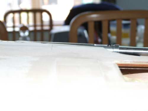
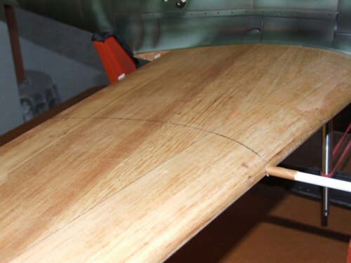
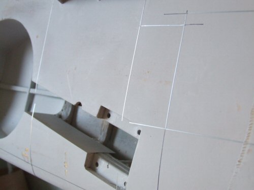
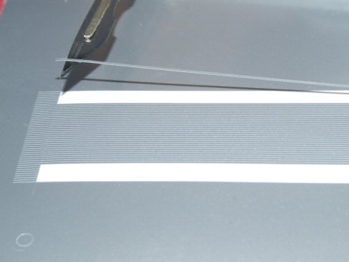
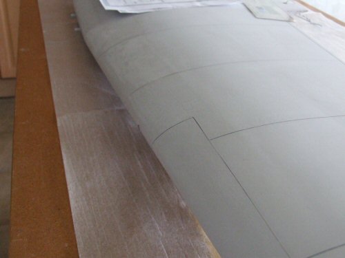
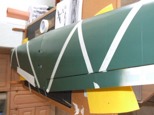
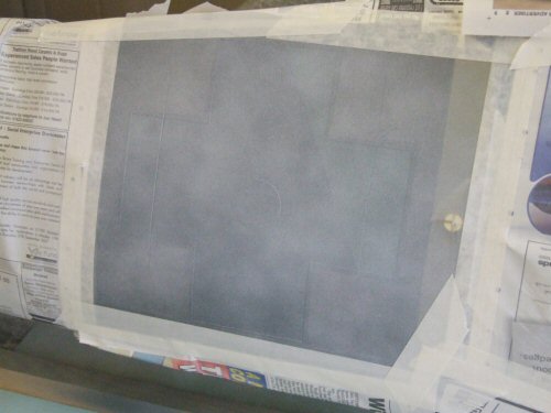
Painting the wing I am going to try out Klass Kote paints. I contacted Mike at Klass-Kote UK for assistance with the colours. Naturally I have a mix of ARTF colours and Humbrol colours to meld together. Anyway I got the colours in so lets see what I can do with them! Pic 1. First job was the primer which sprayed very well. This stuff is epoxy so you have to mix a base paint with a catalyst. I used 60cc primer and 60cc catalyst. 25cc thinners were added to get a good spray pattern. Ambient temperature was 24°C and the paint was touch dry in 40 minutes. Very impressive stuff! Pic 2. Next day I wet & dried the surface. There are a number of bumps and cloth marks in the surface but I am going to carry on regardless. I began marking out the position of the panel lines using reference material. Measurements were all approximate as I didn't want to spend for ever doing this. Pic 3. Panel line tape 0.6mm width was applied to the marked areas. Pic 4. Panel line tape is cut from vinyl and is very easy to apply. Available from Flightline Graphics. By the way Flightline Graphics = me :) Pic 5. Primer was sprayed over the panel tape a number of times to get a build up of paint. Notice the extra length of tape hanging over the edge, well I do this to make it easier to get hold of the tape. Pic 6. Pulling the tape off after the paint had been on for 30 minutes reveals the grooves. |
 |
 |
 |
 |
 |
 |
| 1. Click to enlarge | 2. Click to enlarge | 3. Click to enlarge | 4. Click to enlarge | 5. Click to enlarge | 6. Click to enlarge |
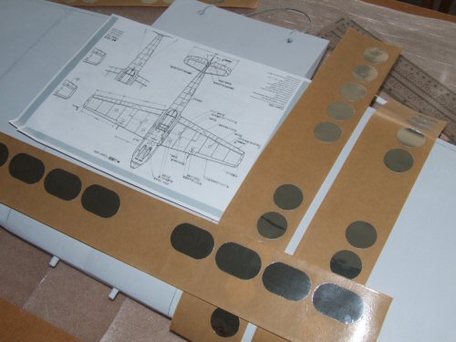
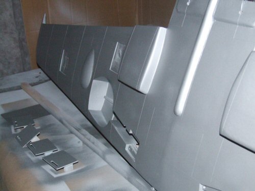
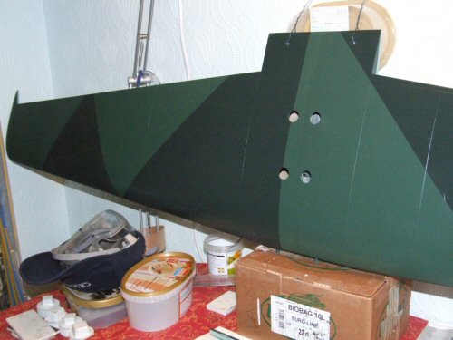
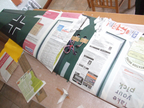
Pic 1. Appearance of the panel lines after a light rub down to level any ridges pulling the tape might have caused. The now exposed black in the lines is the marker pen from drawing out the lines. When paint is applied the lines will not be so defined. Pic 2. Not wanting to over cook things a small smattering of inspection ports were cut for application. Pic 3. applied with sheet aluminium tape. These were rubbed down with the back of a spoon (yes I had permission to use an old spoon) which makes a good press for the tape. The excess aluminium dust on the wings from rubbing the aluminium down was removed with a small amount of denatured alcohol. Pic 4. Next covering is some silver. I am going to rub the wing down to attempt some ware and tare so we need the aluminium under the paint for the correct effect. The paint covers very well with a powerful covering capacity. You can see the amount of pigment in the paint is far higher than most other paints out there. Pic 5. Once dry it was time for the underside to be painted in RLM 65 Hellblau. Other parts were getting sprayed along with the main wing including, 4 x servo panels, wheel covers, aileron & flaps. 6 hours later I did some masking and applied the Dunkelgrun (dark green) to the top surface. 30 minutes after spraying the making was removed and is as seen in the picture. Pic 6. More masking tape in use to add the pattern. Note the ailerons and flaps are installed for this process, but were actually removed for the spraying to make things easy. The Schwartzgrun (even darker green) went on in one easy coat. I mixed a total of 60cc of this paint and could have got away with half! Once again the covering power is incredible. |
 |
 |
 |
 |
 |
 |
| 1. Click to enlarge | 2. Click to enlarge | 3. Click to enlarge | 4. Click to enlarge | 5. Click to enlarge | 6. Click to enlarge |
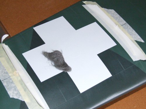
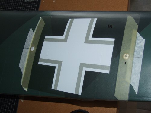
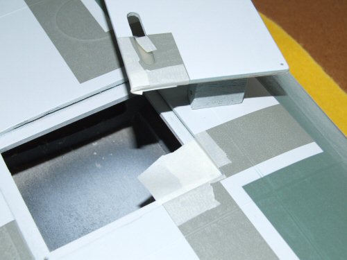
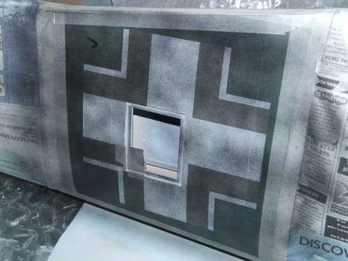
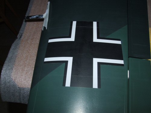
Pic 1. All the masking tape was removed after 30 minutes and the paint was touch dry 10 minutes later. Fantastic! Now it's time for the insignia! Pic 2. As I run my own business now producing Paint Masks for scale models it was easy to get the masks together :) ., If you are interested in using my paint mask systems please contact me via the contact page and I will do my very best to help with with any standard or custom mask you require. Pic 3. Advertising over . . . the secret with paint masks is to build the paint up slowly. Here the first coat of white has been sprayed on and allowed to "flash off" before the next layer is applied. Pic 4. As the paint became touch dry I removed the mask and waited for the paint to cure. Once it was hard I cut the lip around the edge of the white finish with clean "000" wire wool. This removes the unsightly edge from the white and will stop it from showing through the soon to be applied black coat. Pic 5. The mask for the black is applied and ready for painting. Pic 6. Underside the masks run over the servo hatches and need some supplementary masking. |
 |
 |
 |
 |
 |
 |
| 1. Click to enlarge | 2. Click to enlarge | 3. Click to enlarge | 4. Click to enlarge | 5. Click to enlarge | 6. Click to enlarge |
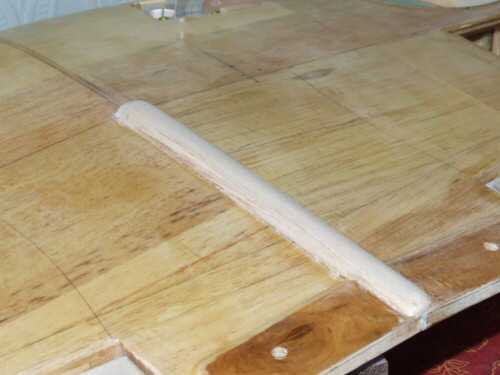
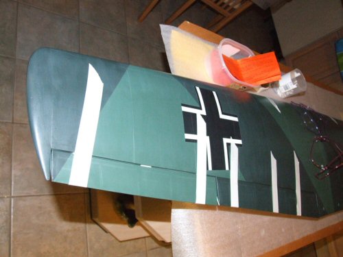
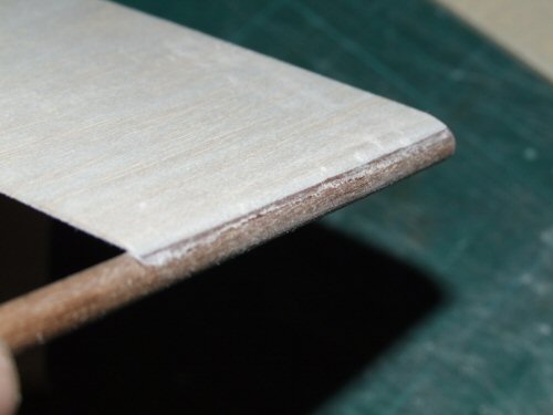
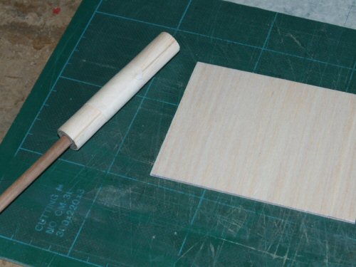
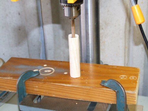
Pic 1. As with the white I am spraying the paint on sparingly over 3 - 4 coats of paint. Pic 2. After drying, and a final rub down with "000" wire wool the menacing insignia takes on life! Pic 3. Now the main painting is over I installed the control surfaces using a new PVA for hinges. Pic 4. Next up some cannons! I start with some 5mm hardwood dowel, and attach a short strip of 1/32" soft balsa with cyano. The first lip is sanded as shown in the picture before soaking the sheet on both sides with Aliphatic PVA and rolling it tightly. Pic 5. The finished item ready for shaping. Pic 6. A hole in a section of hardwood is used as a baring for the hardwood shaft. The other end firmly gripped by a bench press drill. While in the frame I sand the surface down with a sand block to create the correct diameter. Post sanding the wood was sealed with some spare black Klass Kote paint. |
 |
 |
 |
 |
 |
|
| 1. Click to enlarge | 2. Click to enlarge | 3. Click to enlarge | 4. Click to enlarge | 5. Click to enlarge | 6. Click to enlarge |
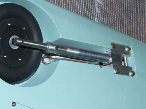
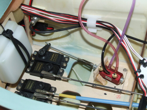
Various other finishing touches to the model Pic 1. The wheels are installed with the Shindin retracts. Pic 2. A Robart valve was installed to operate the air up air down system. Pic 3. I obtained a digital on board glow system to make the starting process much easier. The battery was installed directly next to the main battery in the front compartment under the fuel tank. Pic 4. I decided to add some walkway lines and warnings just for the hell of it :) Pic 5. Using standard enamel paint and paint masks the markings were applied. Pic 6. Not a bad result for a last minute idea! |
 |
 |
||||
| 1. Click to enlarge | 2. Click to enlarge | 3. Click to enlarge | 4. Click to enlarge | 5. Click to enlarge | 6. Click to enlarge |
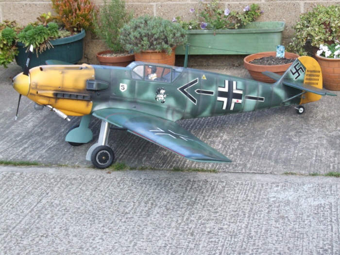
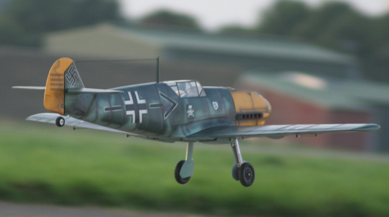
All finished Well after all that the model is finished and ready for flight testing. I re balanced the model to 116 mm which is the official specified point and I wish I had ignored all the forum comments from the USA claiming it was too far back as the first flight went very well indeed and landed with greater ease. |