
YT International P51D - FuselageThe all glass fuselage is highly decorated out of the box and really does show how much the ARF market has developed. YT have a difficult job satisfying the scale "virgins" and experienced scale flyers with a specification that is "scale enough" for the serious modeller, and a" very acceptable" for the newbie! A compromise that is met full on with this kit and I suppose any of the YT scale warbirds now available from YT.
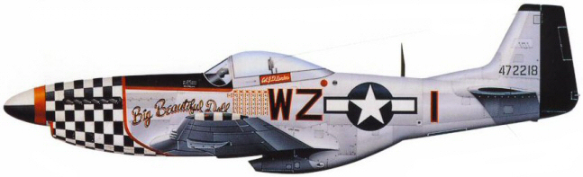
I plan on re-decorating the entire airframe, and hopefully reproduce "Big Beautiful Doll" though I am not 100% set on this Idea it is currently my favourite. (Six Shooter is second favourite) |
 |
I am going to do several things with the fuselage to start the physical changes none of which are really necessary but for me I just want to play!
1. As I am using a Laser engine for this model I am going to re-position the fuel tank. 2. Look at some level of cockpit detailing, though I can't decide how far to go! Maybe a 2 stage effort will be used, having a basic level of detail for the first flight and then adding more when I can. 3. Because of the cockpit work the servo mounts will have to be re-thought. 4. Add retractable tail wheel. 5. Possibly add scoop vent on underside . . . undecided on that one. 6. Detailing may require current rivet holes to be filled or modified so I can add my own detailing. Panel lines may also suffer! |
 |
 |
 |
 |
 |
 |
| 1. Click to enlarge | 2. Click to enlarge | 3. Click to enlarge | 4. Click to enlarge | 5. Click to enlarge | 6. Click to enlarge |
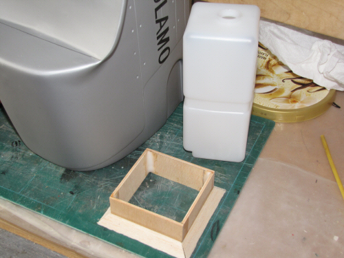
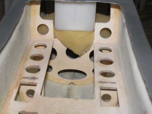
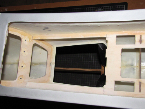
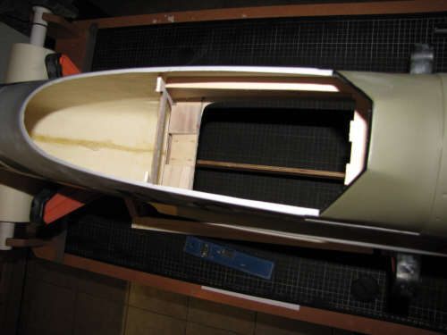
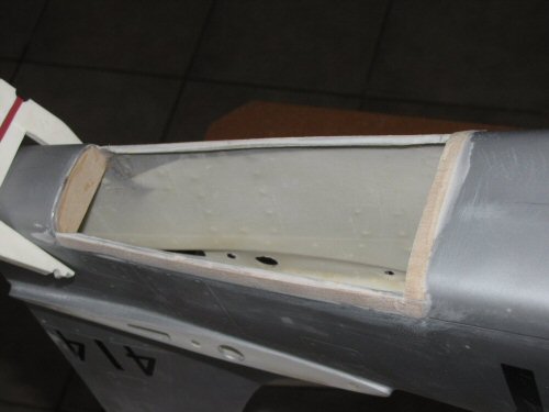
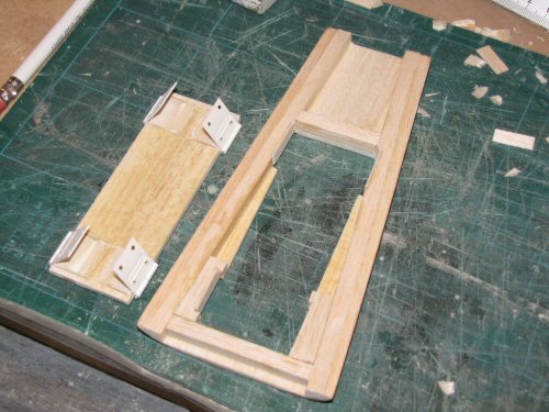
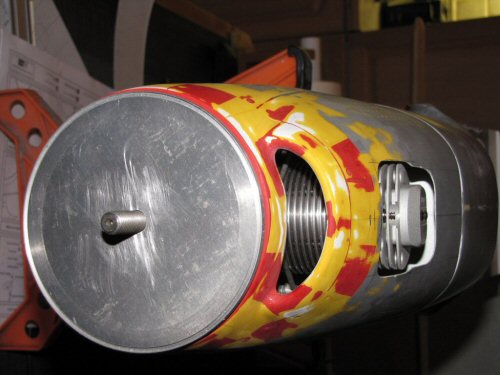
Pic 1. The easy job to start with. I am lowering the fuel tank as much as possible. I plan on using a Laser 150 0r 180 engine which have their carburetor level with the top of the cylinder head, so the tank needs to be much lower than the standard installation. I decided to make a frame to fit on the fire wall which will hold the tank in position much closer to the engine. Pic 2. The frame was fixed in position and a new 25mm hole was drilled for the tank opening to fit into. Pic 3. Shows the view from inside the fuselage. A few sections of wood had to be cut away to gain access for the tank. A lump of foam holds the tank in position temporarily, later when I have all the internals worked out there will be a frame across the back of the tank to hold it securely. Pic 4. More hacking at the fuselage, first I took out the plywood servo tray and the small vertical former that was installed above. Pic 5. With the small former removed it was necessary to carefully sand away the excess resin that had remained on the fuselage walls. Pic 6. Shows the full area cut out with my trusty Dremel. The rear former also had to be trimmed to accommodate fixing of the rear deck where the batteries etc. are stored , which I plan on reproducing. |
 |
 |
 |
 |
 |
 |
| 1. Click to enlarge | 2. Click to enlarge | 3. Click to enlarge | 4. Click to enlarge | 5. Click to enlarge | 6. Click to enlarge |
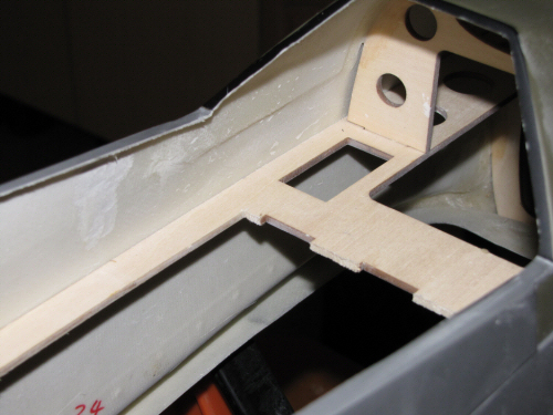
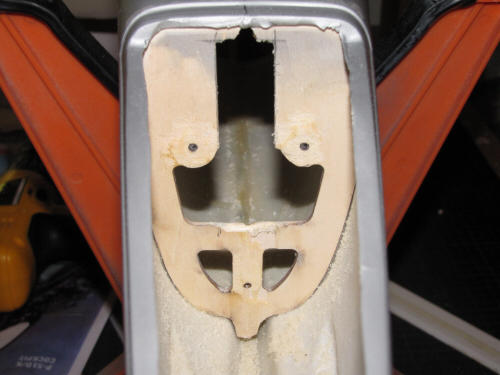
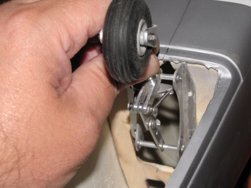
Pic 1. Working at the tail end the retractable tail wheel needs a groove up the centre of the mounting plate, so more wood was removed to enable the mechanism to function. A new section of ply wood will be applied onto the current plate to reinforce the now weakened former. Pic 2. The tail wheel unit is checked for fitment as seen here. I am going to hold off installation until I have the aircraft standing on it's front wheels and I am abel to gauge the correct installation position for the wheel. Pic 3. I will not be using the supplied plastic to make the tail wheel cover. so I started to fill in the recesses that are built into the fuselage. I also installed a small former at the rear of the opening to add some rigidity. Pic 4. Holding everything in place while measured up for the new cover. Pic 5. I made a frame with 1/4" balsa and then sheeted over the top. Once dry I sanded it to shape. The airframe will require a little filler to make the shape continuous. Pic 6. The cover was glass clothed and the openings made for the doors. |
 |
 |
 |
 |
 |
 |
| 1. Click to enlarge | 2. Click to enlarge | 3. Click to enlarge | 4. Click to enlarge | 5. Click to enlarge | 6. Click to enlarge |
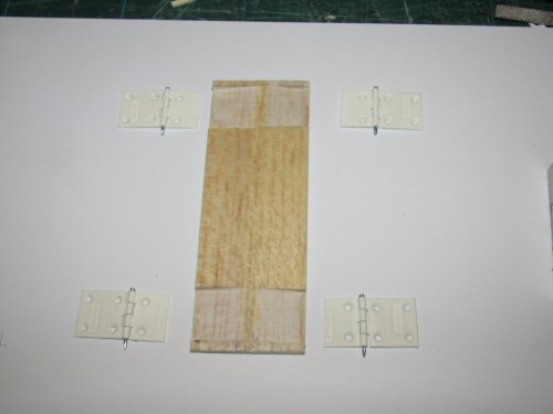
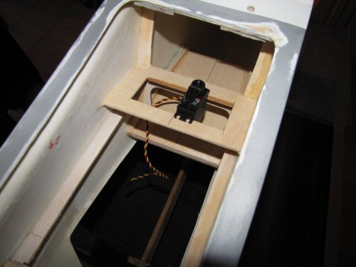
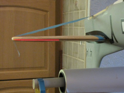
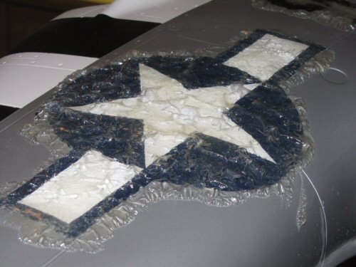
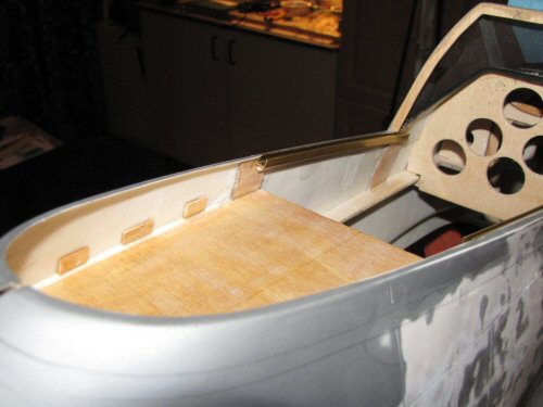
Pic 1. The cut out balsa was shaped to accept standard hinges and reduced in size to allow them to move without catching. Pic 2. The installation was then installed into the cover. It is planned for this part to remain detachable and I have yet to decide on how it will hold in place. Magnets are favourite at the moment. Pic 3. While I ponder the tail end a bit more I have moved to the servo tray which I am fitting behind the pilot. I am only mounting here because I will be using a heavier engine to standard otherwise I would be in front of the pilot. Pic 4. A re-positioned former will permit installation of an instrument panel at some time. For now the light ply will do. Pic 5. The horizontal stabs are mounted on a aluminium tube and locate into the fuselage with some dowels. A ply template is supplied with the kit to locate these holes correctly. I mount the wings and use a laser level to compare reference points in the wings and stabs to ensure alignment. One day I will use the laser for decorating :-\ Pic 6. All attempts to remove the waterslides failed! so out come the big guns. A thin layer of paint stripper was used to remove the top 2K clear coat. Be careful if you use this procedure as I did have a slight reaction with the glass underneath! |
 |
 |
 |
 |
 |
 |
| 1. Click to enlarge | 2. Click to enlarge | 3. Click to enlarge | 4. Click to enlarge | 5. Click to enlarge | 6. Click to enlarge |
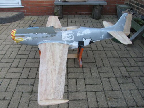
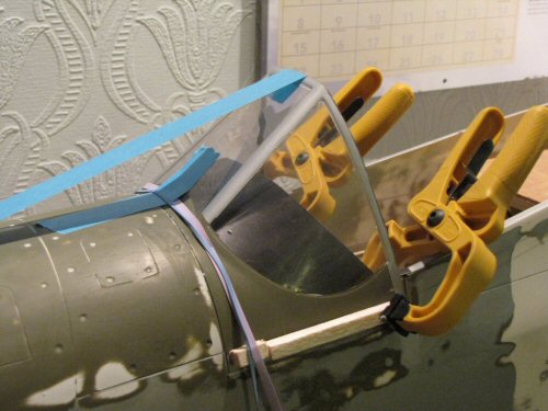
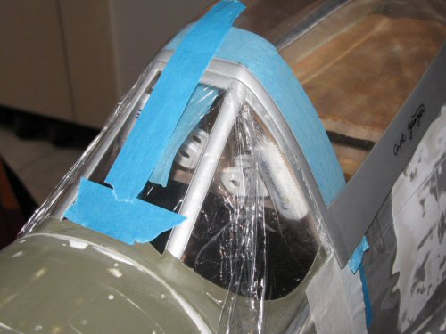
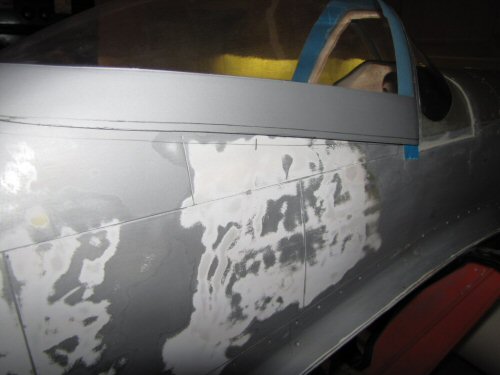
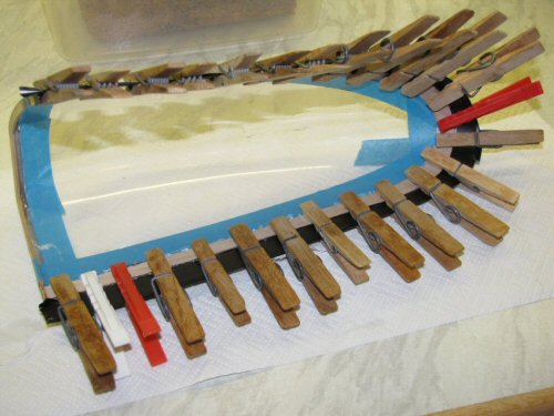
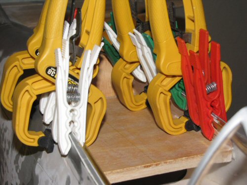
Pic 1. All cleaned up and a visit from the "Wet & Dry" later it's looking a little sad for itself, but then we know it can only get better. Pic 2. While I was sanding I finished everything else off so we are ready for the primer . . . almost! Pic 3. The canopy will slide so I have to carefully cut the molded parts in half. Before cutting I checked the fitment first on the fuselage. Pic 4. The canopy was cut with a steady hand and a brand new blade in my scalpel. Surfaces were then sanded and cleaned before fixing into position with canopy glue. Pic 5. A ply frame was carefully cut and installed into the canopy. The face was finished to a good standard before continuing. Pic 6. A second similar sized frame was cut and held in position over the first frame with clips and a temporary brace to maintain the span. This will become the frame for the sliding canopy, so the area mating surfaces were all protected with cling film and masking tape. |
 |
 |
 |
 |
 |
 |
| 1. Click to enlarge | 2. Click to enlarge | 3. Click to enlarge | 4. Click to enlarge | 5. Click to enlarge | 6. Click to enlarge |
Pic 1. The canopy was fixed in position over the frame with plenty of slow cure epoxy and left overnight. Pic 2. While the epoxy was drying I noticed the starboard side of the sliding canopy frame was lower than on the port side, so I measured it up for a trim later. Pic 3. A veneer of 1/64" ply was shaped around the inside of the sliding canopy to add some rigidity. This lining will also hold the retaining system for the rear canopy and the mid brace which will be installed later.. Pic 4. The canopy needs a track to slide up and down at the rear, so I made a small channel out of ply and balsa, Seen here in the picture just before I added the top sheet. Pic 5. Duly installed into the frame with a channel in the airframe. Pic 6. A small section of good quality ply was carefully cut to form a guider for the canopy and epoxy glued to the canopy while sat in the channel. It was deliberately cut slightly long to make some room for adjustment. The weight was used to hold everything down firmly while the glue set.. |
 |
 |
 |
 |
 |
 |
| 1. Click to enlarge | 2. Click to enlarge | 3. Click to enlarge | 4. Click to enlarge | 5. Click to enlarge | 6. Click to enlarge |
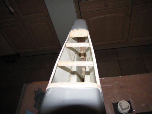
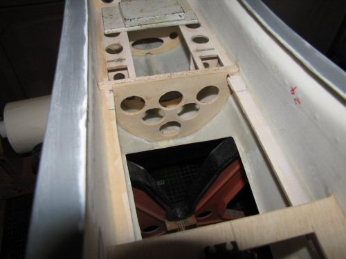
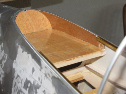
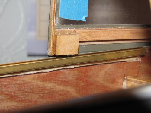
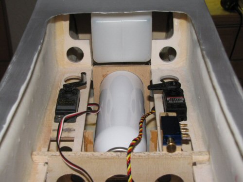
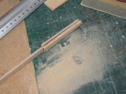
Pic 1. Once the guide was dry I removed it from the channel and began to gut to size. Once achieved I added a pair of hard wood lugs to the end to slide in the pre formed channel. Pic 2. A thin lining of 1/64 ply will be added to the upper cockpit and battery bay. Some small blocks of light ply were first fixed to the skin as shown. Pic 3. The Linings were carefully cut to shape and installed using Thixotropic Polyurethane glue. Pic 4. All installed. The woodwork was given a sealing coat of Z-Poxy to seal the grain. Pic 5. The brass sliding channel was purchased from Mick Reeves and installed using two part methylacrylic adhesive. A small ball joint was mounted into a ply block to secure the front end. Note the ply lining also installed. Pic 6. The air tank I have decided to install in the forward area of the fuselage. A ply frame was affixed to the front former and a spacer attached to the second former to hold it in place. A brace will be used to stop the tank from moving around. The throttle and retract servos will fit on each side of the fuselage with the air valve sitting to the rear of the servo. I might install the valve elsewhere yet as I am not fully decided. The receiver will be boxed and installed behind the fuel tank.
|
 |
 |
 |
 |
 |
 |
| 1. Click to enlarge | 2. Click to enlarge | 3. Click to enlarge | 4. Click to enlarge | 5. Click to enlarge | 6. Click to enlarge |
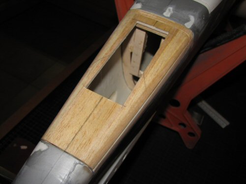
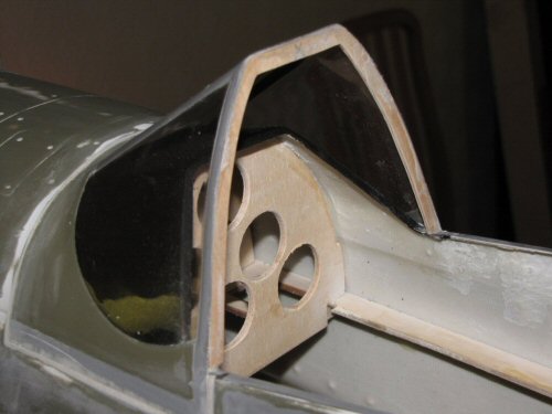
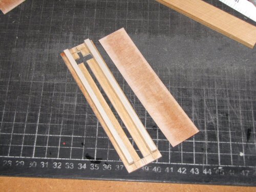
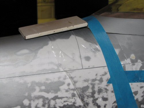
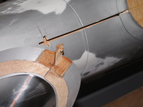
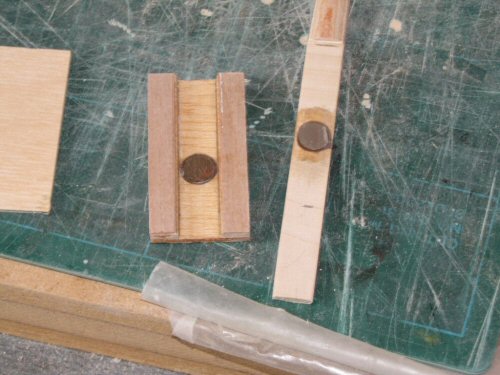
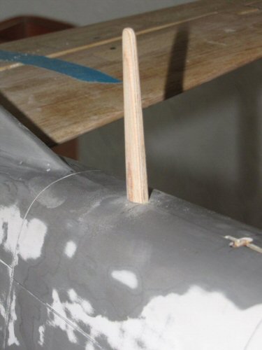
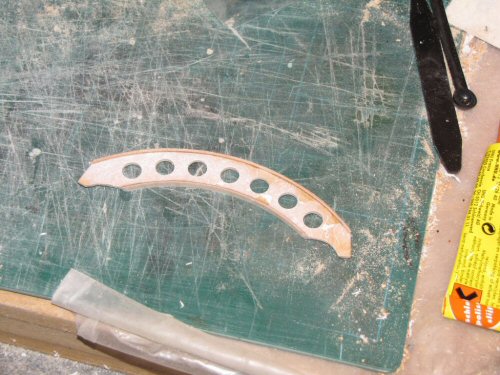
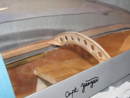
Pic 1. The P51 D has a radio mast installed aft of the canopy track system so I thought I would add a reproduction. I started with some 2mm ply wood and laminated some light ply to each side. The mast was then sanded to shape. Pic 2. A channel for the mast to run in was formed with light ply. A magnet was used in the shaft and the corresponding side of the guide. Care was taken to ensure the magnet was installed at the correct depth. Pic 3. The Slider was then capped off before installing in the fuselage. A "T" former was installed across the fuselage to support the bottom of the guide. Pic 4. All installed and ready to play! Pic 5. I am still not planning to do too much inside the cockpit, but a clearly visible element in the canopy is the steadying brace. I decided to make a plywood version as it would help to hold the canopy true on the model. I carefully drew the design on card first with Corel Draw before producing it from wood. Pic 6. Installed into the canopy, I also decided to add some triangular fillets to improve rigidity. All this will be painted silver later on.
|
 |
 |
 |
 |
 |
|
| 1. Click to enlarge | 2. Click to enlarge | 3. Click to enlarge | 4. Click to enlarge | 5. Click to enlarge | 6. Click to enlarge |
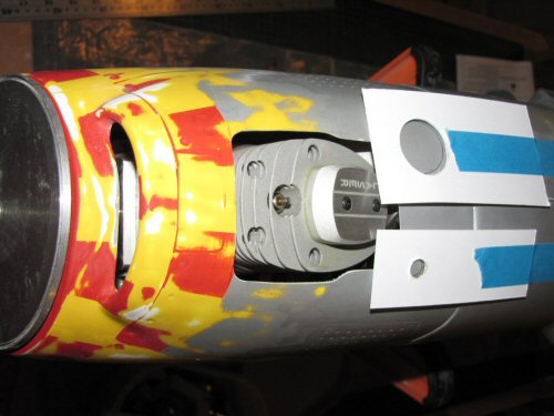
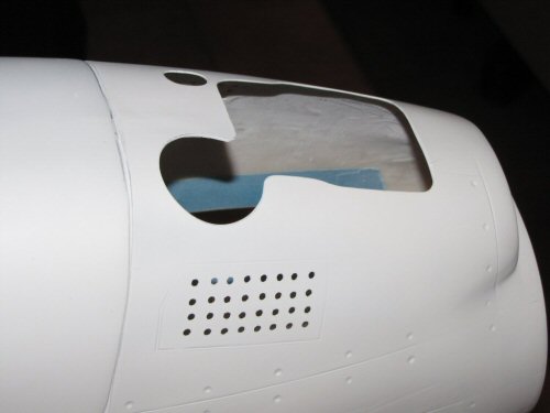
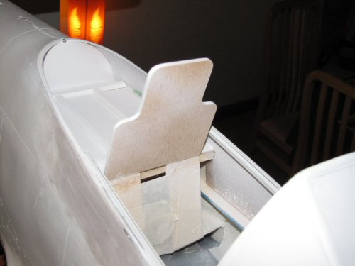
Pic 1. The engine needs a 1/4" shim behind the engine mounts to have a comfortable reach. Everything was installed to test the cowl fitment. Once I had an idea what to do I removed the exhaust and the needle valve and concentrated on the head installation. Pic 2. Carefully cut away with the Dremel the head peeps through a small amount. If I had used the Laser 150 that would have sat within the cowl for sure. These are the penalties of over-sizing the engine! Pic 3. The exhaust and needle positions were noted with card tracers before marking on the cowl for cut away. Pic 4. Unfortunately I lost the last few pictures in the series which showed the cowl cut away. The best I can now show you is an image with the first primer coat ;-( Pic 5. Also lost was an image with the pilots bullet proof plate built from light ply, also shown here after the first primer coat.
That just about wraps up the Fuselage work so it's off the to the garage to put some paint on! Click here. |