
Mick Reeves 1/6 Scale Spitfire Review |
 |
 |
| Click to enlarge | Click to enlarge |
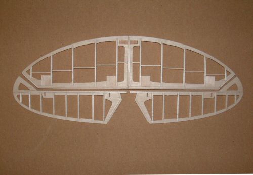
It is some time since I last built a model so I thought I would start with the easy bits, the Stab, Rudder and Elevator. SCRAPPED the supplied stabiliser kits! |
 |
 |
 |
 |
 |
 |
| 1. Click to enlarge | 2. Click to enlarge | 3. Click to enlarge | 4. Click to enlarge | 5. Click to enlarge | 6. Click to enlarge |
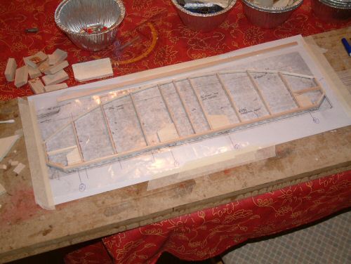
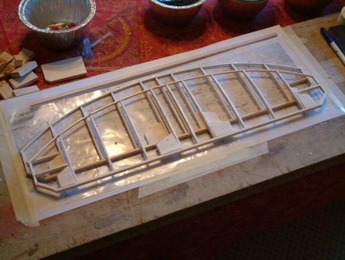
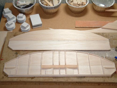
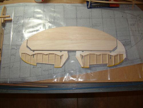
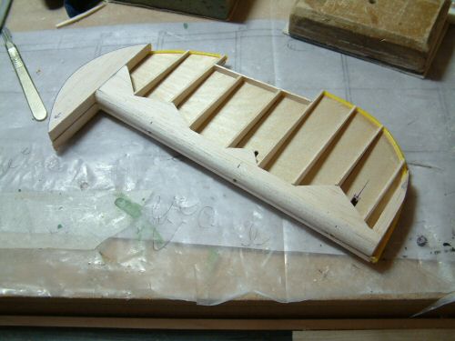
Time to start again, but using a technique similar to those on Bryan Taylor plans. Pic 1. To start I cut the rib halves as per plans 1/32" deeper at the centre to make up for the missing 1/16" sandwich. I also trimmed the front edge 1/16" shorter to accommodate a strip for the front edge which would be laminated later to form the actual leading edge. Additional pieces of balsa are used to make mountings for the elevators which doubled as strengtheners to the structure. Pic 3. and sheeting both sides with 1/16" sheet. The elevator surfaces are made from a core of 1/32" ply and fixing solid light balsa top and bottom to for the structure. Ribs are medium 1/16" and the tip edge is plastic push-rod core rather than aluminium tube as recommended on the plans. Pic 4. Shows the rough cut parts. Pic 5. The completed shaped parts. Pic 6. General top view (right elevator not sanded to final shape). |
 |
 |
 |
 |
 |
 |
| 1. Click to enlarge | 2. Click to enlarge | 3. Click to enlarge | 4. Click to enlarge | 5. Click to enlarge | 6. Click to enlarge |
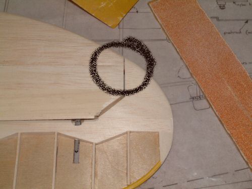
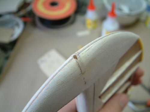
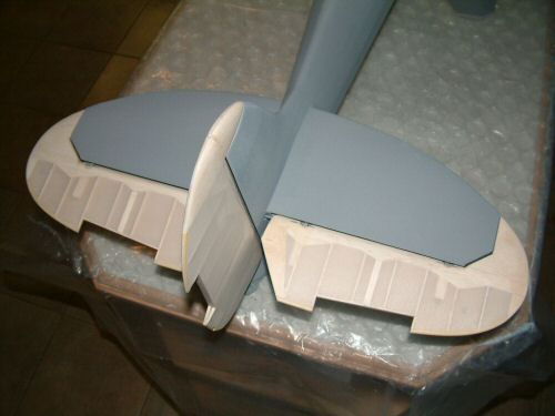
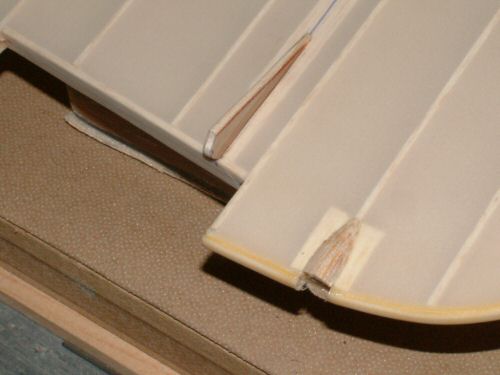
After a short break from the stabiliser surfaces to build the wing and the fuselage I am now making the final touches to the Elevator. I am in actual fact waiting for a replacement fuselage in the form of a wood Kit rather than the glass version. Click here for the full story! While I wait I build. Pic 1. shows additional support between the balance and the stab using scrap 1/32" ply glued with the minimum of cyano (circled). This adds some rigidity to the job when sanding. I also ran a length of masking tape over the rear edge of the stab surface, so as to protect it from the sanding bar. Much care and attention to detail is required to get the surfaces looking just right. I used reference pictures of Spitfires to help in this process. Pic 2. The finished item with the connecting bar installed between the 2 elevator halves. Pic 3. The Rudder was fabricated in much the same way as the elevators. Pic 4. Sanding on the rudder done I installed a small hole in line with the hinges ready to receive a mounting for the antenna. Pic 5. Likewise a slot and some extra scraps of balsa was installed ready to mount the tail navigation light after clothing. Pic 6. A later picture of the control surfaces installed on the primed fuselage. |
 |
 |
 |
 |
 |
 |
| 1. Click to enlarge | 2. Click to enlarge | 3. Click to enlarge | 4. Click to enlarge | 5. Click to enlarge | 6. Click to enlarge |
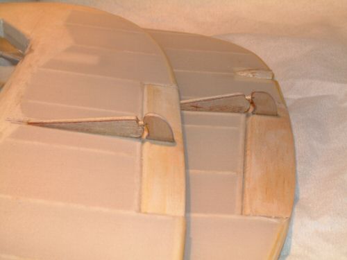
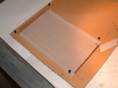
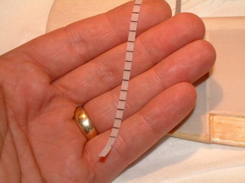
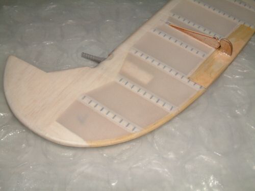
Finally got round to installing the trim systems. Pic 1. The shaft arm installed on all 3 surfaces is made from 3/32" balsa sandwiched between 2 sheets of 1/64" ply and rounded on the top. The fabric was cut to help key the epoxy into the wood support underneath. Here the rudder is shown with the landing light faring similarly installed. Pic 2. The trim tabs are made from sheet balsa and sanded to shape. I experimented with various glues to install the tabs and found Formula 560 Cockpit Adhesive worked very well. Pic 3. The trim tabs were fabricated from 1/16" balsa sandwiched between sheet 1/64" ply sanded to shape. The connecting rods were simply cocktail sticks sanded slightly finer. Pic 4. To start with a pin board was marked out with 2 rows of tack pins every 5mm. A sheet of Solartex was put between the tacks sticky side up, with the film removed. Cotton was stretched between the pins and fastened to the Solartex with Balsalock. Pic 5. Strips 3mm wide were cut from the sheet for application along each strut line with an iron. Pic 6. Once applied a 6mm sheet was placed over the top and ironed down firmly. |