
YT International P51D - WIngsThe wings come ready decorated with a special film YT now use on all their scale warbirds. It is claimed to be less prone to wrinkles and blemishes even after a period in the sun. I have tested this by putting a wing outside for a few hours on a very hot day and there were indeed no blemishes that you would normally expect to see taking a conventionally covered ARF outside for the first time!
I am going to do a number of alterations.
1. Remove the covering from the wing. 2. Reinforce the undercarriage woodwork with epoxy and additional wood if required. 3. Install conventional hinges for the ailerons. The landing flaps already have these installed as standard. 4. Build in the cannons so they are a little more convincing than the vacuum formed plastic parts supplied. 5. Line the wheel wells with balsa or thin ply. 6. Close the open frame on the underside of the wings (3 panels on each side) 7. Cover with glass cloth and resin. 8. Add some panel lines to the wing. |
 |
 |
 |
 |
 |
 |
| 1. Click to enlarge | 2. Click to enlarge | 3. Click to enlarge | 4. Click to enlarge | 5. Click to enlarge | 6. Click to enlarge |
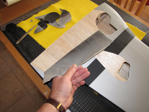
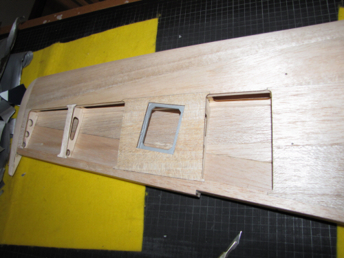
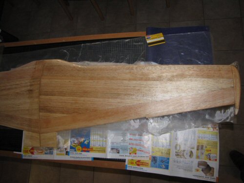
Pic 1. First things first, the covering needs to be removed to provide access to the framework. While it can be fun ripping the covering off it has to be done with care not to damage the fibres of the balsa. Where possible you should pull the covering off in the same direction as the grain to prevent lifting the fibres. Interesting to note, the covering was very well keyed to the surface of the wood, far better than the solartex covering on the ME109 as I recall. Pic 2. All removed the covering exposes the build of the wing. Generally the workmanship is very good and finished to a good standard. I will be touching a few things up before glassing, but I am impressed with what I see. The wing weighed 656g with no aileron or flaps installed before stripping the film, and after it weighed 562g, so it will be interesting to see if the glassing adds more than 94g when I get to it . Pic 3. I test fitted the retract in the wing with OLEO and wheel installed. I think they fit very well in the space provided so don't think there is going to be a problem. The wood for mounting the retracts on is the typical laminated ply sheets we see in ARF kits. Some extra strength will be added later to help the airframe survive my landings! Pic 4. I traced around the open frame sections with a pencil on a sheet of paper to get a template for the 3/32 balsa sheet. A bit like brass rubbing I suppose :) Pic 5. Small supports for the balsa sheeting are added to make it easy to align the sheeting with the existing skin. Pic 6. All sheeted up using the templates and roughly sanded in this picture. |
 |
 |
 |
 |
 |
 |
| 1. Click to enlarge | 2. Click to enlarge | 3. Click to enlarge | 4. Click to enlarge | 5. Click to enlarge | 6. Click to enlarge |
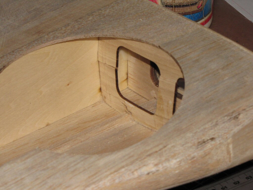
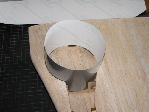
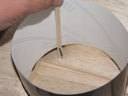
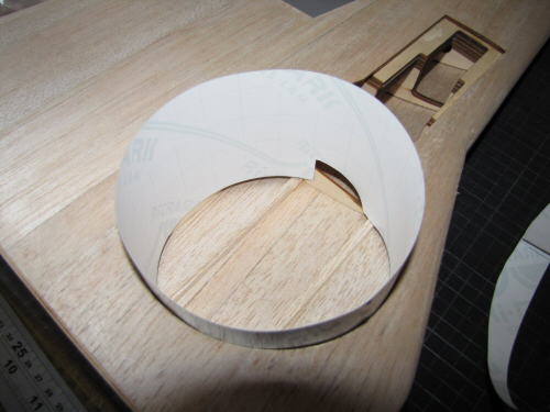
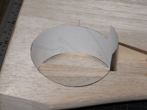
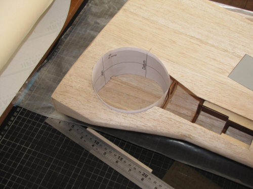
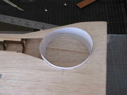
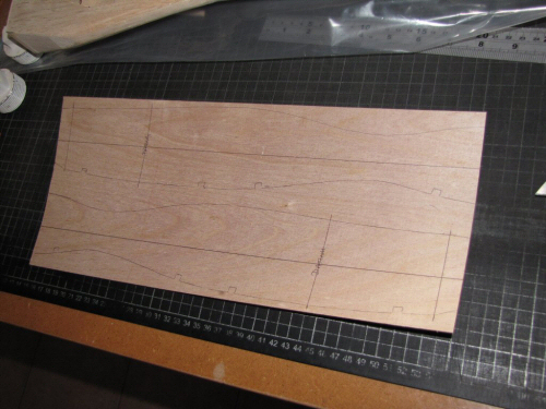
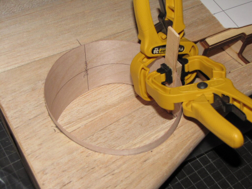
A number of people have asked in the past for me to give more details on how I line the wheel wells. So here we go with slightly more detail than I would normally spoil you all with ;-) Pic 1. Ideally you need a perfect tube from the mouth of the well where the sheeting is right down to the bottom where you meet the underside of the top wings sheeting. On the inner side of the well is a rib that has been visibly damaged to make it fit correctly, I say this because the rib in the other wing is exactly the same, and It appears to be done so as to fit closer to the root on the lower skin. I have decided not to try trimming the rib but I will adapt everything to take these discrepancies into account. Pic 2. The whole process starts by working out the circumference of the the well. For those of you who don't remember its π x D (3.14159 x 125 = 393mm) so I need to make a tube 393mm long on the circumference. I use an old cut of vinyl to do this, and it's best if it is a single sheet of material! The tube goes straight down until it touches something! Pic 3. A narrow strip of balsa with a small hole is used to hold a graphite tip. The hole is positioned slightly longer than the largest gap visible in the tube to the upper wings skin. Carefully following the contours of the well I draw the shape of the base on the tube holding the pencil as close to the tube as possible. I also mark a datum on the tube to correspond with a fixed point on the wing so I can align it in the same position later (not visible in picture). Pic 4. The tube is removed from the wing and the line is carefully trimmed with scissors. Pic 5. Re-introduced to the wing the tube sits on top of the 5mm spars. You should trim only if they are way out here! Pic 6. The top edge is cut flush with the wing. Note the Datum line which is now visible at the top of the picture. |
 |
 |
 |
 |
 |
 |
| 1. Click to enlarge | 2. Click to enlarge | 3. Click to enlarge | 4. Click to enlarge | 5. Click to enlarge | 6. Click to enlarge |
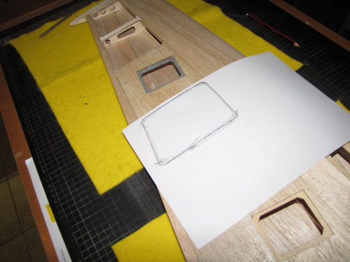
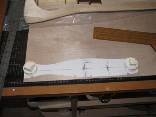
Pic 1. With the tube trimmed I remove it from the wing and cut roughly in the position where the OLEO would pass through (you will see why later). Pic 2. I take the template, scan it into my computer, and trace the outline with vector software. On the top site (which equates the lower wing skin) I add 20mm or so to the top edge so there is some room for trimming! I also add a flap at one end so the ends can be joined together. The new template is printed onto paper and returned to the wing. Note: because the dimensions are greater than the length of a sheet of A4 paper I print in 2 halves carefully joined together with sticky tape. Once added back to the wing and aligned with the datum point, I mark the positions of the spars and cut them out with a knife. I re-fit several times until I get a satisfactory fit to the wing skin (this is why we have some extra on the paper template!). Pic 3. The template now removed and again cut in the OLEO position. I scan this more accurate template into my computer and make the necessary corrections with the new outline adding the cut outs for the spars as I go. I add a smaller 10mm extra to the upper edge for any emergency trimming that might be required. Pic 4 & 5. The new template, now in light card is inserted for final fitting and trimming. Pic 6. Shows the the final template sat on the 1/64" ply ready for tracing. |
 |
 |
 |
 |
 |
 |
| 1. Click to enlarge | 2. Click to enlarge | 3. Click to enlarge | 4. Click to enlarge | 5. Click to enlarge | 6. Click to enlarge |
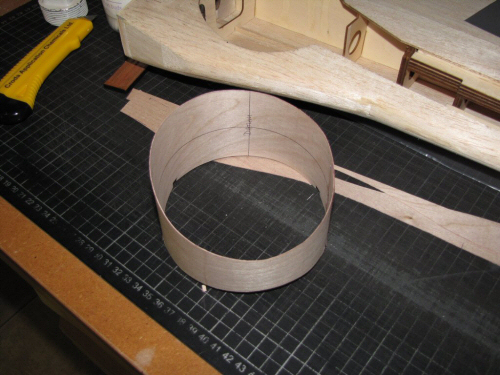
Pic 1. When tracing make sure you do a reversed pattern for the opposite well !! Pic 2. the ply is cut out and test fitted to the wing. Again trim if necessary then when happy with the fit the tube can be made complete by overlapping the tab and lacing it with cyano to make a quick joint in situ. I allow this to set for 10 minutes to be sure it has gone off before removing. Picture taken while waiting for glue to dry! Pic 3. Once removed the well is finally ready for fixing in position. Pic 4. I use Aliphatic PVA to fix these parts as it is easier to sand compared to standard PVA when dry. Allow to dry thoroughly! Pic 5. White the linings were drying I sanded the Flap and Aileron servo doors to profile on the wings. The inner servo covers required a skin of 1/32" balsa to build them up to make the profile. Pic 6. All dry now so the lining can be carefully opened up with a Dremel to clear access for the oleo. I have used some scraps of balsa to fix behind the skin to add some support where I was sanding otherwise the 1/32" ply could split when cutting.
|
 |
 |
 |
 |
 |
 |
| 1. Click to enlarge | 2. Click to enlarge | 3. Click to enlarge | 4. Click to enlarge | 5. Click to enlarge | 6. Click to enlarge |
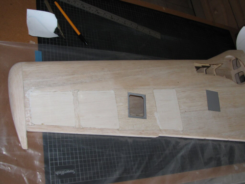
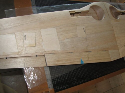
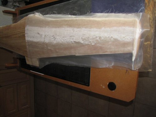
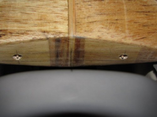
Pic 1. I built up redundant parts of wheel wells with scraps of balsa and part lined with 1/32" ply. The lining is shown here un-trimmed as the PU adhesive had not yet cured. Pic 2. Flaps and Ailerons installed dry to check spacing and to mark the positions of hinges and centre lines for control horns. Pic 3. On all my scale models I replace the felt hinges with mechanical pin hinges (purely a personal choice and not strictly necessary). Also visible is a screed of finishing glass resin which has been applied very thinly over most of the wooden structure. This was necessary as the fibres of the balsa were slightly damaged when the film was removed. Before glassing I will give the wing a light sanding to smooth it down. Pic 4. The inside edge of the wheel wells was filled with some lightweight filler to hide any small imperfections that were there. The entire well area will be varnished several times once dry and lightly sanded. Pic 5. Rather than have raised domes on the top surface of the Ailerons and Flaps for the control horns I drilled a tight countersunk hole from the top surfaces and passed through bolts saturated with epoxy. Once installed all excess was removed from the threads with Acetone and the slightly sunk head of the bolts were filled in with lightened epoxy. Pic 6. Glassing now underway on the wing with 24g/M2 cloth. The undersides have been completed in this picture and I was sizing the cloth for the top wing. When I do the undersides I wrap as much over the edges as possible, and for the trailing edge I wrap all the way to the top edge. This makes the top sheet a low hassle application so I can concentrate on the finish. |
 |
 |
 |
 |
 |
 |
| 1. Click to enlarge | 2. Click to enlarge | 3. Click to enlarge | 4. Click to enlarge | 5. Click to enlarge | 6. Click to enlarge |
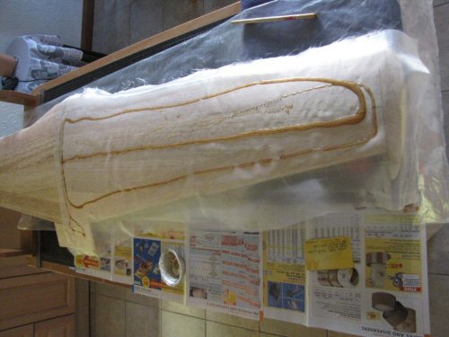
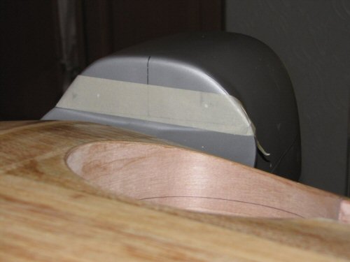
Pic 1. After mixing the Z-Poxy resin I allow it to stand for 5 minutes before pouring it over the cloth. I do this to stop the reaction in the pot generating too much heat and setting the resin off too early. . . . It works for me! Pic 2. All applied and squeegee 'd out with an old Credit Card. Pic 3. After trimming the excess cloth and a quick sanding I test fitted the wing in the fuselage and made sure I was satisfied with the alignment before drilling the locating dowel holes. To drill the corresponding holes in the fuselage I get some dowel and sharpen it in a pencil sharpener. Inserted into the holes the pointed tips can be seen just proud of the surface. I then add some marker pen ink or other material to transfer it's position onto the fuselage. Here I am using a small amount of Aliphatic PVA so you can see the tips. Pic 4. The wing has to be lowered in position in one smooth action otherwise you will end up with a smudged line. The markers show up nicely. I usually drill to the tighter side of the hole to make the fit as snug as possible. Pic 5. The rear fixing screws were drilled and the blind nuts glued to the inside of the fuselage (no pics). With the wing fully mounted the air scoop under the wing can be seen here to have a bit of a poor fit. Pic 6. shows a 2.5mm shim at the trailing edge making up the difference. |
 |
 |
 |
 |
 |
 |
| 1. Click to enlarge | 2. Click to enlarge | 3. Click to enlarge | 4. Click to enlarge | 5. Click to enlarge | 6. Click to enlarge |
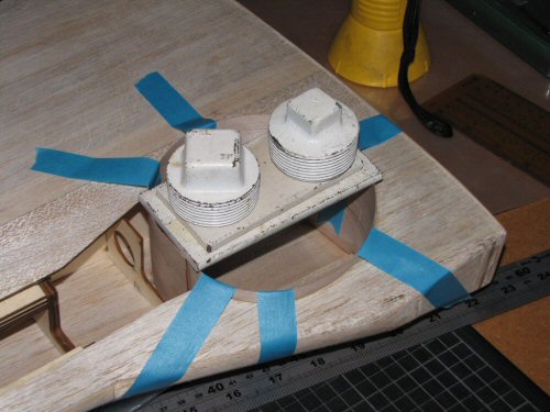
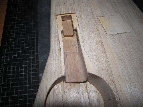
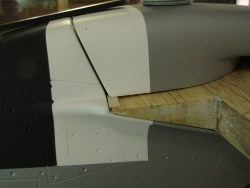
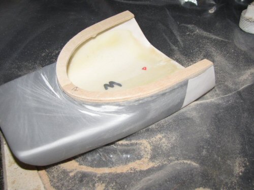
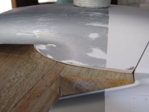
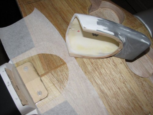
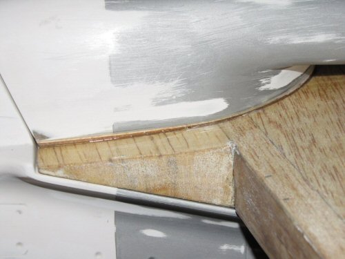
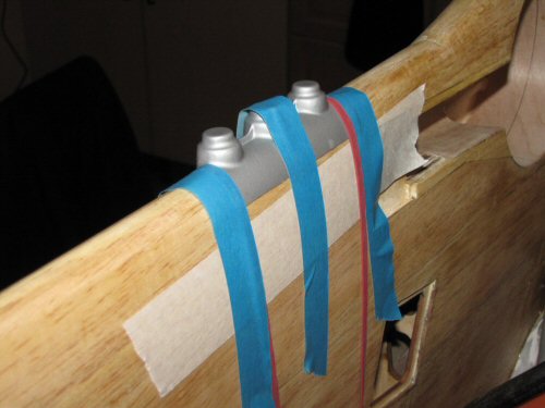
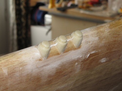
Pic 1. The mounting surface of the scoop was cut back to remove the paint to get a good key for the ply fillet. I have added 3mm all over and will sand it back to fit. Pic 2. After a little sanding and shaping the fillet makes good on the fitment . This part will be fixed after I have wet and dried the wing. Pic 3. Wet & Dry complete the outline of the scoop was drawn onto a tack sheet and the outline cut out. This will save any excess glue (epoxy) going where it shouldn't Pic 4. Duly installed, the tape was removed after a quick wipe over and we have a nice clean line. When I get some filler out later I will render a small fillet into the corner. Pic 5. I did not want to install the plastic gun faring's supplied with the kits as they are too exaggerated for the frame. After some consideration I decided to use them as a mould! I got some casting resin, waxed the internals of the plastic, roughened the wing leading edge to key the casting resin and they were on! Pic 6. Just after removing the mould the covers look much more convincing. A little excess resin around the edges was carefully removed with sandpaper. |
 |
|||||
| 1. Click to enlarge | 2. Click to enlarge | 3. Click to enlarge | 4. Click to enlarge | 5. Click to enlarge | 6. Click to enlarge |
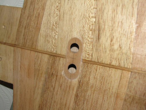
Pic 1. Adding the ply liners to the wheel wells has made it difficult to install the air lines down the leading edge of the wing as per the instructions. I have therefore made it possible to route the air lines and all the servos to a new location on the wing. I added some 1/32 ply to the outlet to offer some support to the wood.
The Wing construction is now concluded and will move over to the painting section. |