
Mick Reeves 1/6 Scale Spitfire Review
|
 |
 |
 |
 |
 |
 |
| 1. Click to enlarge | 2. Click to enlarge | 3. Click to enlarge | 4. Click to enlarge | 5. Click to enlarge | 6. Click to enlarge |
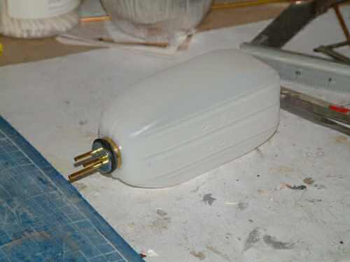
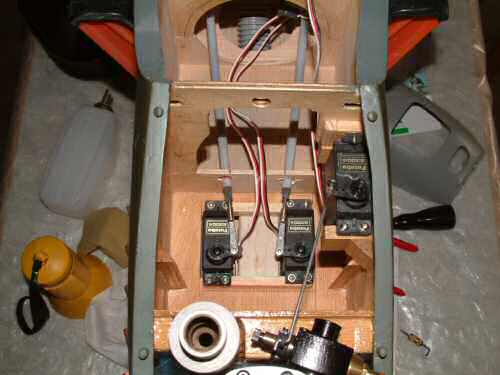
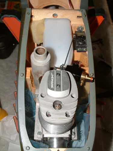
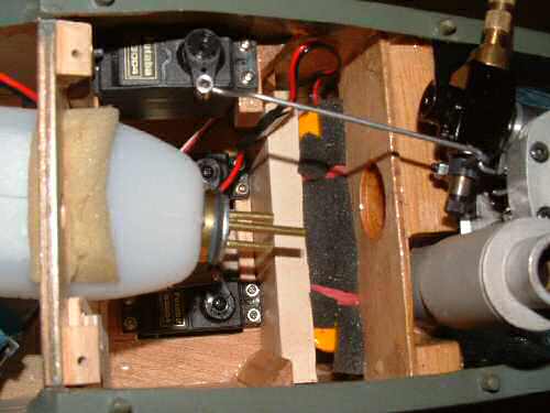
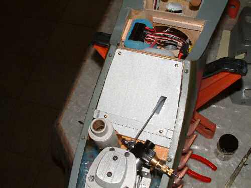
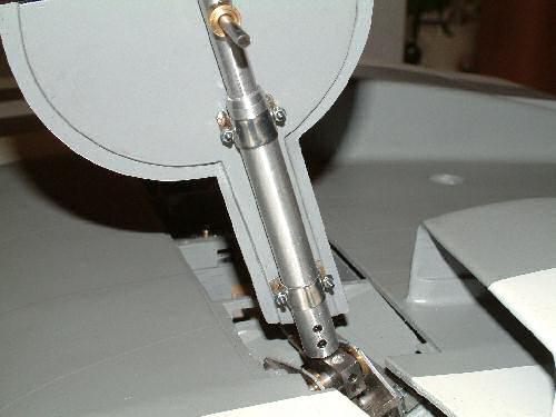
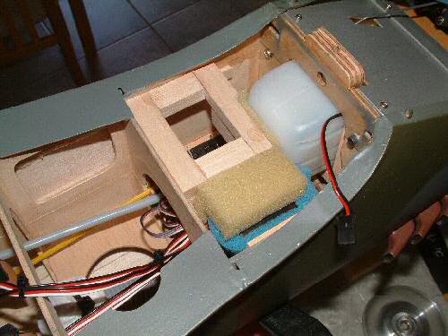
After a short break from the build I am finally back building the Spitfire!. Pic 1. The tank ia a 350ml Kavan tank which should give a good 10 minutes in the air. On large tanks I install a short length of metal tube in the fuel feed to help prevent the clunk becoming trapped. Pic 2. Installed and ready to play. The tank has been tested to ensure it is air tight in a large bowl of water. I never assume the tank is sealed just because it is new! Pic 3. The landing flap servo leads need to be extended to bring the connections to the centre of the wing. Because these wires are buried within the wing I run cotton round the connection to hold them together. Pic 4. The outer and inner flaps are connected with a wire bent at the appropriate angle. My original plan was to run the servos on one channel with a "Y" cable, however in practice it proved easier to manage by using separate channels on the RX (CH 7 & 8) to permit individual adjustment of each side. Pic 5. Shows the general layout of the servos. The rudder (right) and elevator (left) servos are in position and have been adjusted accordingly. Note the 2 triangular sections in front of the servos on the box wall, these will retain a plate that supports the batteries behind the firewall. Pic 6. The throttle servo has been connected to the carb and the fuel tank is temporarily held in position. This gives a good general feel for how things will be installed. |
 |
 |
 |
 |
 |
| 1. Click to enlarge | 2. Click to enlarge | 3. Click to enlarge | 4. Click to enlarge | 5. Click to enlarge |
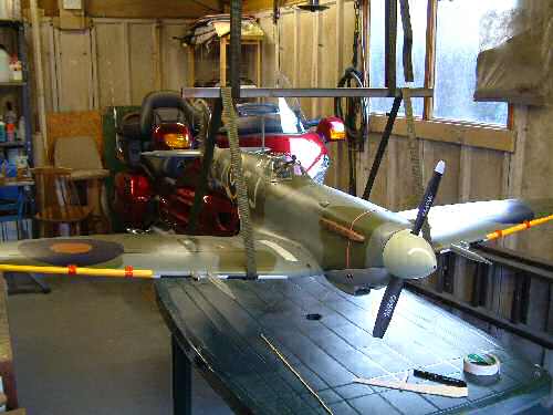
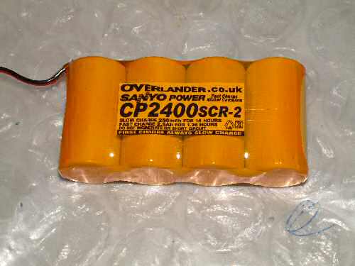
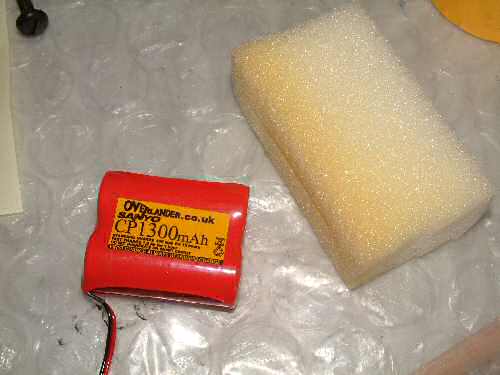
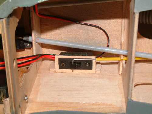
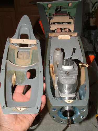
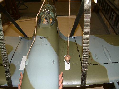
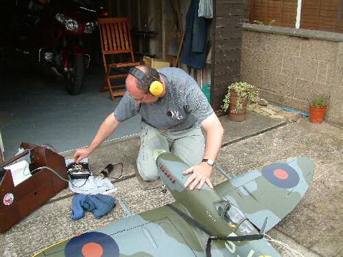
Before purchasing any batteries I dropped 2 standard 700mAh batteries which come to about 130g in behind the firewall to see where the balance (CG) is sitting before I add the rest of the hardware. Pic 1. Shows the model in the sling and interestingly the balance point is only 4.0 cm from the plans recommended point at 119mm from the leading edge. Batteries! I have seen many debates about powering models. Some favour 2 batteries & 2 switches directly into the receiver. Others use diodes on the +ve terminals to protect the good battery should the other fail. Some up to 6v batteries with the diodes to protect the voltage drop caused by the diode. Having listened to the modellers, and the battery manufacturers views on this I am going to install one good battery and one good switch. The mechanical retracts will be powered by a separate battery. I am sure some of you will be saying don't be silly you must protect against a faulty battery, well I am using a good brand of battery (Sanyo) and switch (Futaba heavy duty) which is the recommendation of some modellers and the battery manufacturers. Pic 2. The RX battery is a 2400 mAh sub "C" sell unit with 240g of weight to it. With a claimed 40A discharge this is functional weight rather than lead! Pic 3. the retract gear motor is a 1300 mAh battery at 140g rated with a 30A discharge. This is well over spec for what is needed, but will fit nicely in behind the firewall so also adds some functional weight. Pic 4. shows the Futaba heavy duty switch mounted in a frame to permit removal should it be necessary. Note the retaining bracket on the right former in the picture. Pic 5. The connecting wire passes through to the cockpit and is just visible on the inside of the starboard canopy running track. |
 |
 |
 |
 |
 |
 |
| 1. Click to enlarge | 2. Click to enlarge | 3. Click to enlarge | 4. Click to enlarge | 5. Click to enlarge | 6. Click to enlarge |
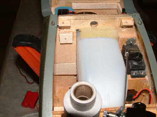
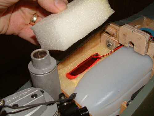
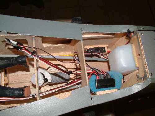
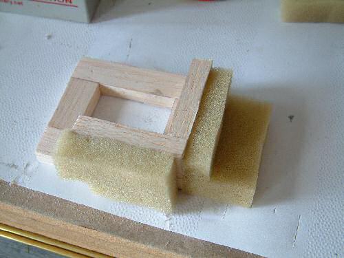
| Pic 1. Shows the RX battery nicely tucked away behind the firewall wrapped in foam. A strip of 1/16" ply bridges the braces preventing the battery from Interfering with the servos. Pic 2. Because I had stupidly cut the fuel tank hole in Former F21 bigger than required, I have fitted a small brace retained by a screw to hold it in position. This does make the tank fit very snug in position. Pic 3. The retract motor battery will fit alongside the fuel tank. First a fillet and foam is installed to make the foam stand off from the servos Pic 4. The battery covered in foam is installed, followed by more foam on top. Pic 5. Covered by a sheet of 1/16" ply to give some protection from the engine bay. These components will be fuel proofed later. Pic 6. The front cowl now has mounting points installed front and back which will be retained with 2 x 3mm key bolts. Note also the brass tube behind the hole for the cylinder head in the cowl. This will provide the forward open (pressure) line to the fuel tank. The newly installed wood parts will all get painted & fuel proofed later. |
 |
 |
 |
 |
 |
 |
| 1. Click to enlarge | 2. Click to enlarge | 3. Click to enlarge | 4. Click to enlarge | 5. Click to enlarge | 6. Click to enlarge |
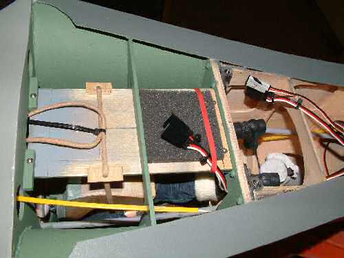
| Pic 1. The receiver is mounted on the side wall with ties retaining it in position. Connectors are installed for the various channels and marked accordingly. I always mark the right connector on all of my models so there is no confusion. Position is the other indication of function. Simple and it works for me! Channel assignment is as follows: Channel 1: Aileron - right,
Channel 2: Elevator,
Channel 3: Throttle,
Channel 4: Rudder, Channel 5: Retract servo switch,
Channel 6: Aileron - left, Channel 7: Flaps - right, Channel 8: Flaps - left .
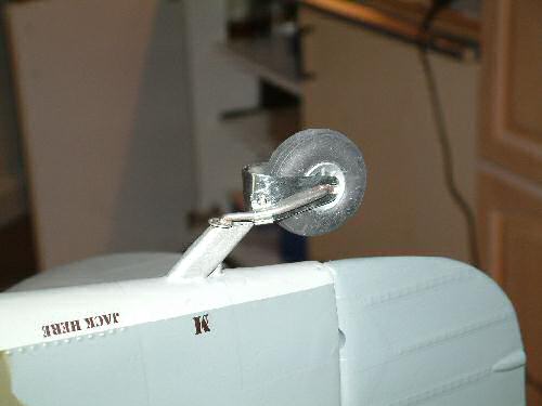
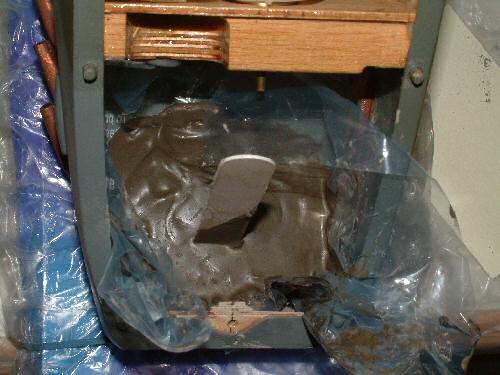
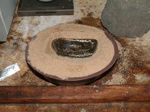
Pic 3. The tail wheel skirt is fabricated from tin sheet and secured to the shaft with a bracket. If I was doing this again I would have built it much more scale like. As it is it's OK for now! Pic 4. Back in the sling in flight ready condition the balance point has hardly improved with the extra weight of the batteries. I attached a cup to the front of the nose and began to load up the lead. 470g later she was there, just over a British Lb. According to form this is not unusual so we accept the punishment gracefully. Pic 5. The plumb weight is spot on. Pic 6. Engine and mounts out a cast was made of the top inside profile of the bay using quick drying filler. This gives a plug to make sand mould. |
 |
 |
 |
 |
 |
 |
| 1. Click to enlarge | 2. Click to enlarge | 3. Click to enlarge | 4. Click to enlarge | 5. Click to enlarge | 6. Click to enlarge |
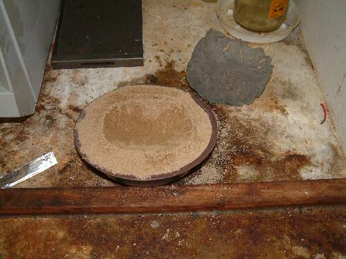
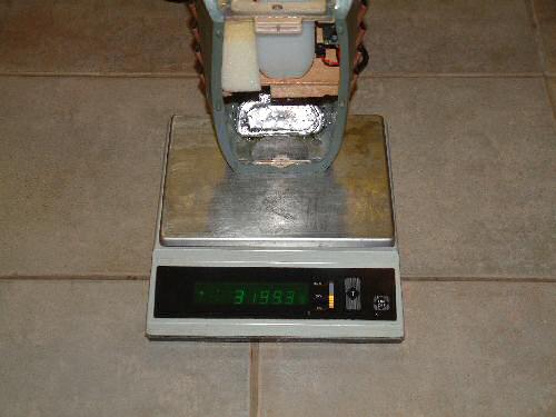
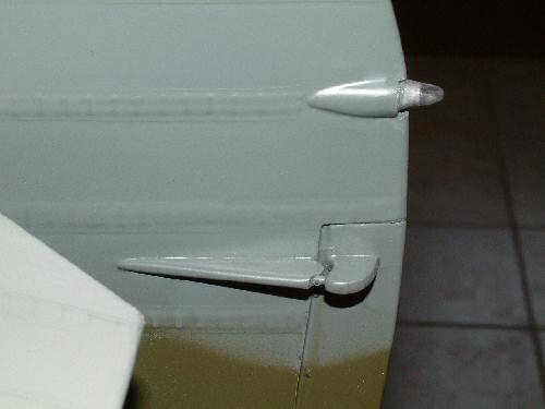
| Pic 1. Very slightly damp sand was used as the mould seen to the back of the sand tray. Using a furnace set at 400°C the lead melted out in about 20 minutes and Pic 2. the lead was cast. Pic 3. The plug was epoxy glued into position once the surface in the bay was etched to give a good bond. Picture shows the fuselage getting weighed on accurate laboratory scales. Final gross weight for the entire model come out at 7.4 Kg (16Lb) much higher that the claimed build weight of 12Lb by Mick Reeves. From what I am reading on the net this is more typical of the weights other builders are experiencing in reality (though at the top end of the range I have to admit). I am slightly disappointed at the final weight, must try harder next time! Pic 4. To mount the wheel covers to the OLEO legs I tried several ideas before settling on the final system. I started with a 10mm strip of tinplate carefully sized and folded at each end. I then flood soldered some brass tube to each end as central as possible. Pic 5. Wrapped around the oleo legs and held together with 2mm key bolts. Pic 6. Wheel covers in position. Picture also shows the gun shell outlets which have been painted into position from reference books. |
 |
 |
 |
 |
 |
 |
| 1. Click to enlarge | 2. Click to enlarge | 3. Click to enlarge | 4. Click to enlarge | 5. Click to enlarge | 6. Click to enlarge |
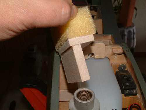
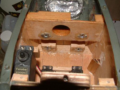
| Pic 1. To retain the fuel tank and add additional support to the receiver a small plug was made from some scrap balsa and foam. Pic 2. Installed in position the tank and receiver are truly secured. Pic 3. Engine test 1. (see the video) Everything looked OK for a while but after about 30 seconds on full throttle I noticed the spinner slip out of alignment. Pic 4. Very poor!! Inspection revealed the rubber mounts were not providing sufficient grip, so I will strip out the front end and install clout bolts to the back of the firewall. It will be fiddly but clearly necessary. Fortunately no damage caused. Pic 5. Clout bolts installed plus a few splashes of epoxy to hold them in position. This installation took a full evening to achieve because of the confined area. Pic 6. While I was installing the clout bolts I installed the tail lamp. To give it more strength I installed a small dowel, painted it silver and then installed the lens with cockpit glue. |
 |
 |
| 1. Click to enlarge | 2. Click to enlarge |
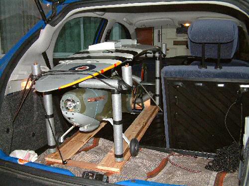
| The last set of pictures!! Pic2. Question: How many Spitfires can you get inside a Peugeot 206. Answer 1. Simple jig made from copper pipe and insulation holds the model nicely for transport. |